Reciprocating compressor

A compressor and reciprocating technology, applied in the direction of liquid variable capacity machinery, electromechanical devices, mechanical equipment, etc., can solve the problems of reduced compression efficiency, inconsistent center, increased manufacturing process, etc.

Inactive Publication Date: 2003-07-02
INTELLECTUAL DISCOVERY CO LTD
View PDF0 Cites 7 Cited by
  • Summary
  • Abstract
  • Description
  • Claims
  • Application Information

AI Technical Summary

Problems solved by technology

[0019] However, in the conventional reciprocating compressor, when the supporting portion 112 is installed, due to the bolt engaging groove 150 of the first frame 104, the bolt through hole 162 of the second frame 142 and the bolt through hole 164 of the third frame 144 are in the After joint bolts 160 are arranged on the same line and then engaged with each other through the joint bolts 160, this requires precise processing of each structural member so that the center of the bolt joint groove 150 is aligned with the bolt through holes 162, 164, thus resulting in manufacturing The process increases and the installation process is complicated
[0020] In addition, when the first, second, and third frames 140, 142, and 144 are installed, the center of the piston 124 may not be consistent with the center of the cylinder 130 due to manufacturing errors of each structural member, and therefore, parts wear will occur, and the operation noise and thus reduce compression efficiency
[0021] In addition, concentrated stress acts on the bolt through holes 150, 162, 164 of each frame due to the joint force of the joint bolts 160, which may damage the holes during operation.

Method used


Image

  • Reciprocating compressor
  • Reciprocating compressor
  • Reciprocating compressor

Examples


Embodiment Construction

[0050] Preferred embodiments of the reciprocating compressor of the present invention will be described below with reference to the accompanying drawings.

[0051] There are several embodiments of the reciprocating compressor of the present invention, the most preferred embodiments of which are described below.

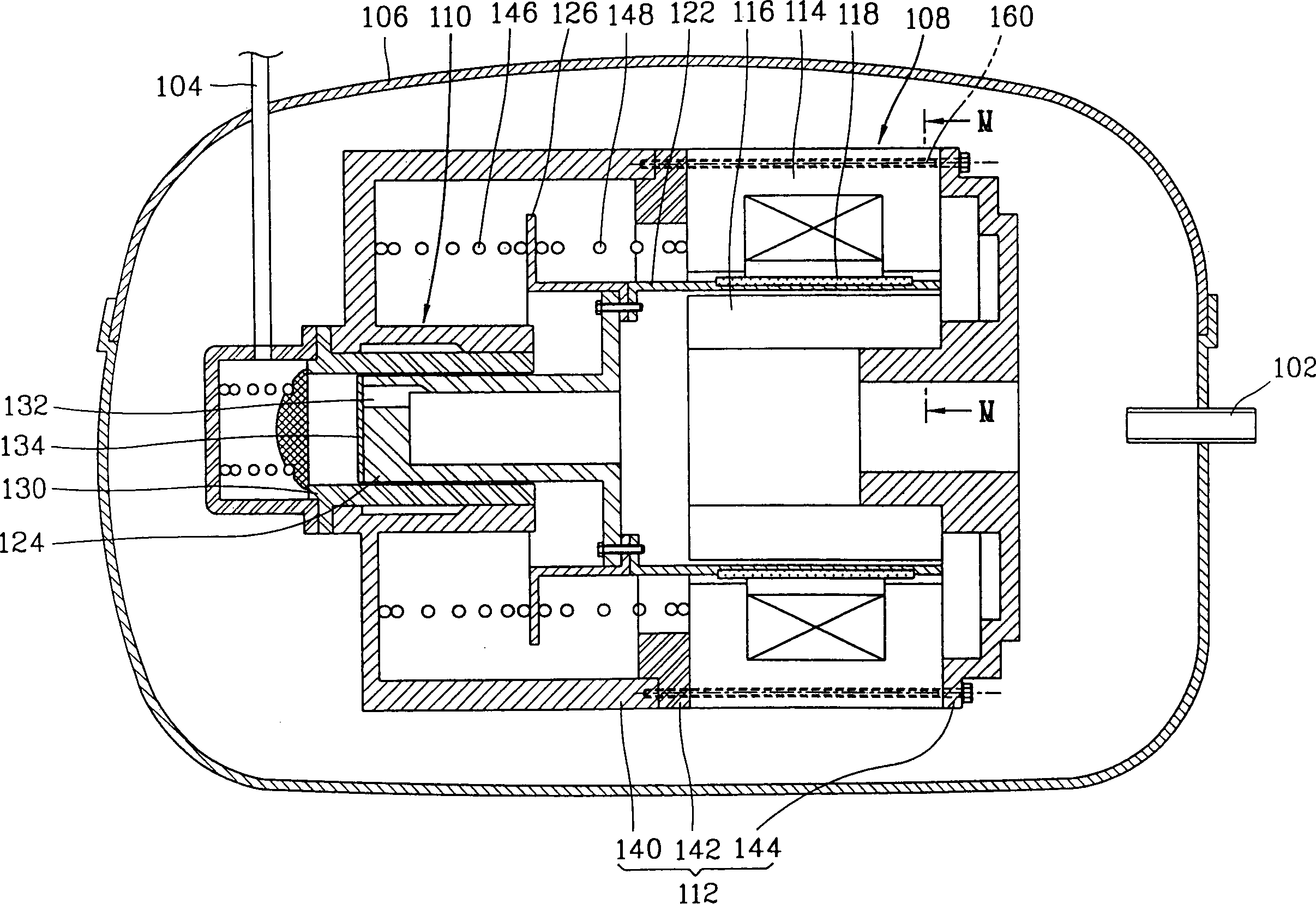
[0052] Figure 4 is a sectional view showing a reciprocating compressor according to the present invention.

[0053] The reciprocating compressor according to the present invention includes a hermetic casing 2; a motor unit 4, which is arranged in the casing 2 and generates a reciprocating force when the power is turned on; a compression unit 6, which receives the reciprocating force generated by the motor unit 4 and performs a compression operation of fluid; and a support unit 8 for supporting the motor unit 4 and the compression unit 6 .

[0054] A suction pipe 9 for sucking fluid and a discharge pipe 10 for discharging compressed fluid are engaged with the hermet...


PUM


Abstract

In a reciprocating compressor including a first frame for supporting a cylinder of a compressing unit, a second frame for supporting a side of an outer stator of a motor unit and a third frame for supporting the other side of the outer stator and an inner stator of the motor unit, wherein the motor unit is arranged between the second and third frames, they are combined with each other, and the assembly is combined with the first frame. Accordingly, a reciprocating compressor is capable of reducing a fabrication cost by eliminating precise processing of construction parts and simplifying an assembly process by constructing a reciprocating motor as one assembly and combining it with a compressing unit.

Description

technical field [0001] The present invention relates to a reciprocating compressor, in particular to a reciprocating compressor capable of simplifying the installation process and improving the installation strength by forming a reciprocating motor as an assembly and combining it with a compression unit. Background technique [0002] Generally, reciprocating compressors are classified into rotary compressors, reciprocating compressors, scroll compressors, and the like according to fluid compression methods. [0003] Reciprocating compressors use a reciprocating motor to drive pistons to reciprocate to compress fluid. [0004] figure 1 A sectional view showing a conventional reciprocating compressor. [0005] A conventional reciprocating compressor includes: a sealed casing 106 to which a suction pipe 102 and a discharge pipe 104 are joined; a motor unit 108 which is arranged in the casing 106 and generates reciprocating force; receiving reciprocating force and compressing...

Claims


Application Information

Patent Timeline
Patent Type & Authority Applications(China)
IPC IPC(8): F04B39/14F04B17/04F04B35/04H02K33/16
CPCY10S417/902F04B35/045F04B17/04
Inventor 朴景培许钟泰卢基元李宰模崔基喆
Owner INTELLECTUAL DISCOVERY CO LTD
Why Eureka
Try Eureka