
Symmetric chromatic separated gratings

A color separation and symmetrical technology, applied in the field of color separation gratings, can solve the problems of misalignment of phase steps on the phase plate of alignment error, double frequency light residue, etc., and achieve the effect of solving the residue

Inactive Publication Date: 2003-06-18
SHANGHAI INST OF OPTICS & FINE MECHANICS CHINESE ACAD OF SCI
View PDF0 Cites 9 Cited by
  • Summary
  • Abstract
  • Description
  • Claims
  • Application Information

AI Technical Summary

Problems solved by technology

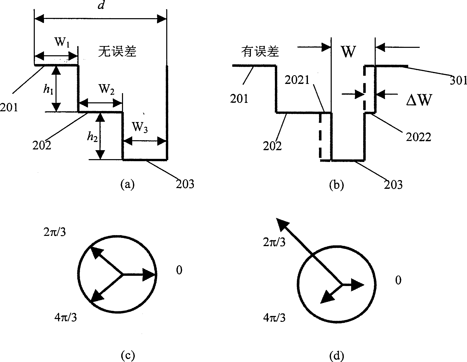
Using the previous design method, the alignment error between the templates will lead to the mismatch of phase steps on the phase plate, resulting in part of the fundamental frequency light and the double frequency light remaining in the optical path of the triple frequency light, and the phase distribution is as follows figure 1 as shown in (d)

Method used


Image

  • Symmetric chromatic separated gratings
  • Symmetric chromatic separated gratings
  • Symmetric chromatic separated gratings

Examples


Embodiment Construction

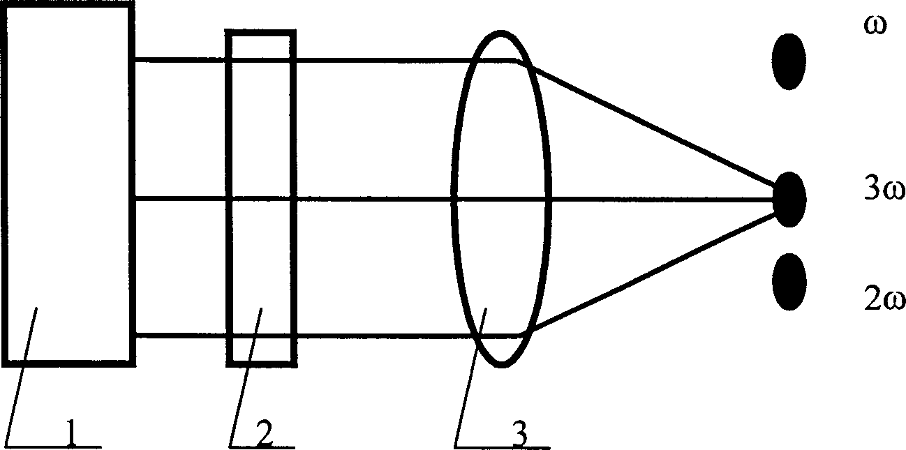
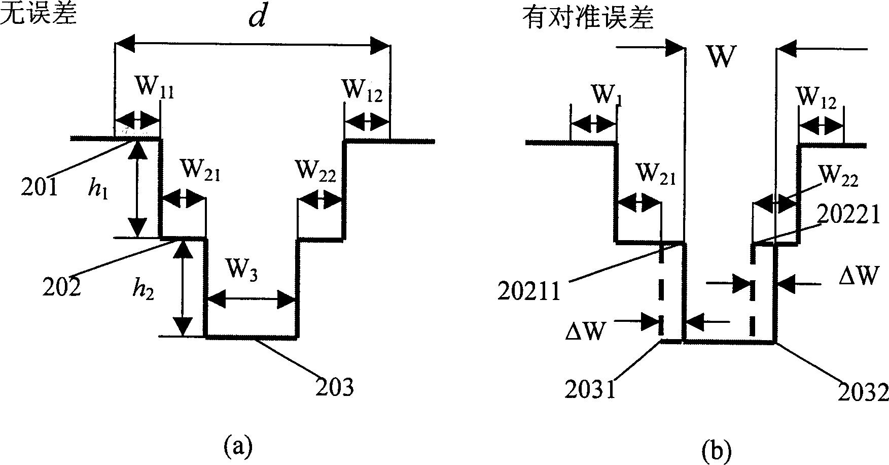
[0023] first please refer to image 3 and Figure 4 . The use of symmetrical color separation grating in the optical path is as follows: Figure 4 as shown, Figure 4 1, 3 functions of optical components and figure 2 It is exactly the same as in , here only the symmetrical color separation grating 2 is used, and its phase distribution is completely symmetrical. The parts from left to right are: W 11 , W 21 , W 3 , W 22 , W 12 ,like image 3 As shown in a, for fundamental frequency light, its phase distribution is: 0, 4π / 3, 8π / 3, 4π / 3, 0, for double frequency light, its phase distribution is: 0, 2π / 3, 4π / 3, 2π / 3, 0, therefore, after the fundamental frequency light and the double frequency light pass through such a symmetrical color separation grating, they will be symmetrically distributed on both sides of the focal point of the converging lens, such as Figure 4 shown. For the frequency tripled light, the depth of each stepped phase is an integral multiple of 0 or...


PUM


Abstract

The present invention relates to a kind of symmetric type color separating grating. Each cycle of the grating includes three steps of phase, which is characterized in that it has a center symmetric configuration with the lowest notch in each cycle at the center of the cycle. The depth of these three steps of phase is h1=h2=lambda / n-1, the sums of the width of each step of phase are equal: wl1+wl2=w21+w22=w3, and all parts of each step are equal: wl1+wl2=w21=w22=d / 6, wherein * is wavelength of incident base frequency, d is cycle of the grating, n is refractive index of the material of the substrate. The color separating grating of the invention can solve effectively the remaining problems of the light with the base frequency and double frequency resulting from the error of alignment of the module plate.

Description

technical field [0001] The invention relates to a color separation grating for separating triple frequency light from fundamental frequency light and double frequency light, especially a symmetrical color separation grating manufactured by binary optical technology, which can eliminate overlay templates Inter-alignment error, improve yield, reduce cost, and facilitate manufacturing. Background technique [0002] In many applications such as laser processing, cutting, cleaning, and laser material modification, we often need tripled light for optical experiments, because shorter wavelength lasers interact better with matter. In fact, due to reasons such as laser triple frequency conversion efficiency, the fundamental frequency (ω) light, double frequency (2ω) light, and triple frequency (3ω) light are all mixed in the optical path. We hope that the required frequency (3ω) The light can be kept running in the optical path, and other unwanted frequency light can be filtered out...

Claims


Application Information

Patent Timeline
IPC IPC(8): G02B5/18
Inventor 周常河
Owner SHANGHAI INST OF OPTICS & FINE MECHANICS CHINESE ACAD OF SCI
Learn More