
Projection display

An image display device and projection technology, which is applied in the direction of using the projection device image reproducer, projection device, image communication, etc., can solve the problems of blurred projection image, different spectral characteristics, and dominant position, and achieve easy plane accuracy, reduce Manufacturing cost, effect of obtaining plane accuracy

Inactive Publication Date: 2003-04-16
PANASONIC CORP
View PDF0 Cites 7 Cited by
  • Summary
  • Abstract
  • Description
  • Claims
  • Application Information

AI Technical Summary

Problems solved by technology

On the downside, there are the following problems: (1) If the combination accuracy of the four prisms constituting the color synthesis optical system 105 cannot be guaranteed, there will be a longitudinal line at the joint surface in the center of the projected image; (2) the color synthesis optical system The reflective surfaces 125, 126 of the system 105 are all set to share the same mirror surface with the dichroic mirror surfaces of the two prisms. If the spectroscopic properties of the two dichroic mirror surfaces forming each reflective surface are different, color unevenness will occur; (3) If the dichroic mirrors of the two prisms that form the reflective surfaces 125, 126 are not formed on the same mirror without distortion and offset, focal blurring such as overlapping will occur on the projected image; Add relay optical system 103 on 102, so just make device large-scale, also have because the light source image of the colored light of passing through relay optical system relatively does not pass through the light source image of two colored lights of relay optical system reverse up and down, can be in Color unevenness occurs when the brightness of the light source or illumination optical system is uneven
On the downside, there are the following problems: (1) Astigmatism occurs due to the light passing through the obliquely arranged parallel plates, and the focus position at the vertical line and the horizontal line deviates, making the projected image blurred; (2) Due to the thin glass plate The dichroic mirror surface formed on it is difficult to meet the flatness requirements, resulting in blurred projected images; (3) the structure of the color synthesis optical system 204 is relatively large, and it is difficult to obtain sufficient mechanical strength, so the ability to withstand external forces such as vibrations is weak. Difficult to maintain spotlight accuracy
In particular, the two problems (1) and (2) are fatal obstacles to the miniaturization and high-definition of LCD screens
Therefore, the orthogonal prism method, despite the above-mentioned problems to be solved, still occupies a dominant position

Method used


Image

  • Projection display
  • Projection display
  • Projection display

Examples


Embodiment 1

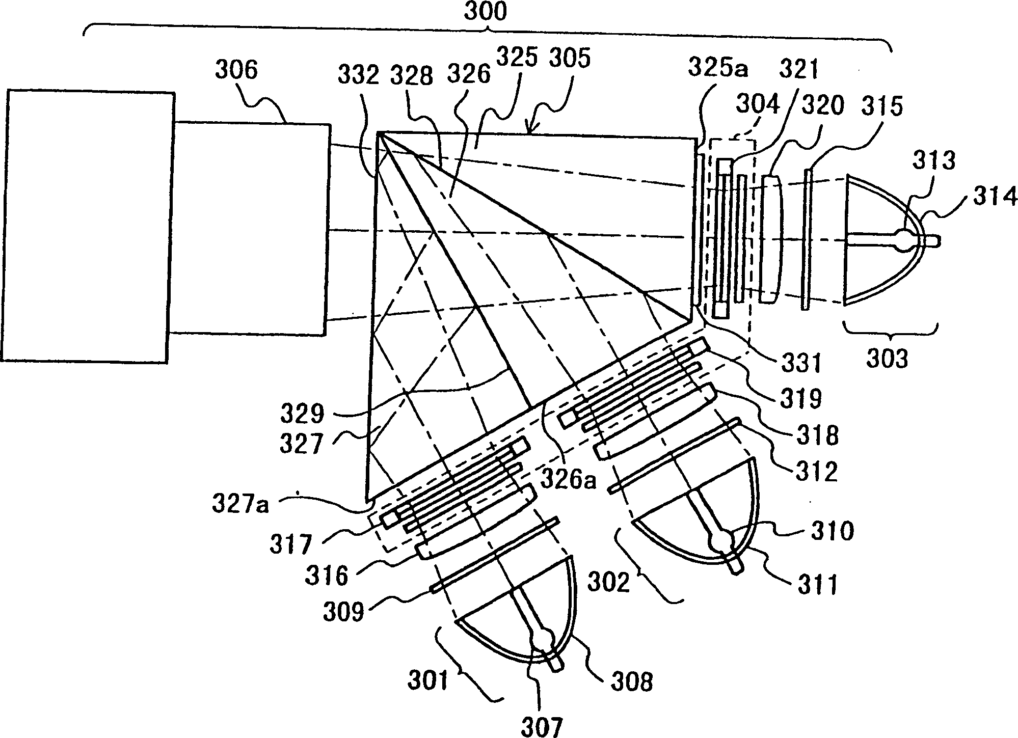
[0059] figure 1 It is a schematic configuration diagram of a projection type image display device according to Embodiment 1 of the present invention.

[0060]The projection type image display device 300 of the present embodiment 1 is composed of a light source part 301 for red light, a light source part 302 for blue light, a light source part 303 for green light, a light valve part 304, a color synthesizing optical system 305, and a projection optical system (projection lens). 306 composition.

[0061] The red light source part 301 is provided with: a light source 307 that emits white irregularly polarized light by forming an electric arc through discharge between electrodes, a reflector 308 that reflects light from the light source 307 in a certain direction on its rotational symmetry axis, and The red-transmitting color selection mirror 309 is arranged in front of the opening of the reflecting mirror 308.

[0062] The blue light source part 302 is provided with: a light s...

Embodiment 2

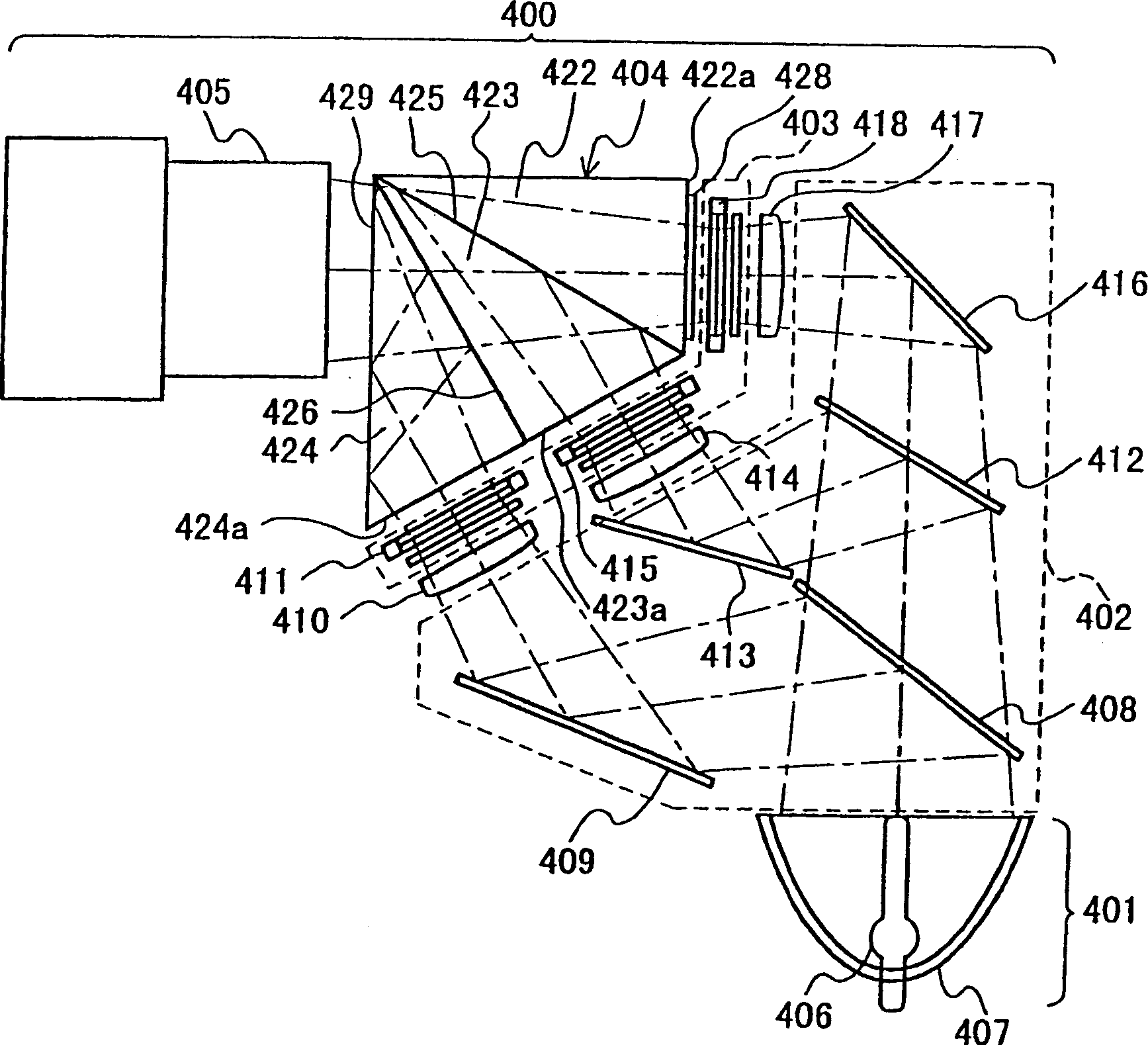
[0083] image 3 It is a schematic configuration diagram of a projection type image display device according to Embodiment 2 of the present invention.

[0084] The projection type image display device 400 of the second embodiment is composed of a light source part 401 , a color separation optical system 402 , a light valve part 403 , a color synthesis optical system 404 and a projection optical system (projection lens) 405 .

[0085] The light source part 401 is provided with: a light source 406 that generates white irregularly polarized light through discharge between electrodes to form an arc, and a reflector 407 that reflects light from the light source 406 in a certain direction on its rotational symmetry axis.

[0086] Light from the light source section 401 is incident on the blue reflecting dichroic mirror (first dichroic mirror) 408 of the dichroic optical system 402 . Among the white light incident to the blue reflecting dichroic mirror 408, the blue light (third colo...

Embodiment 3

[0109] Figure 5 It is a schematic configuration diagram of a projection type image display device according to Embodiment 3 of the present invention.

[0110] The projection type image display device 500 of the third embodiment is composed of a light source part 501 , a color separation optical system 502 , a light valve part 503 , a color synthesis optical system 504 and a projection optical system (projection lens) 505 .

[0111] The light source part 501 is provided with: a light source 506 that generates white irregularly polarized light by forming an electric arc through discharge between electrodes, and a reflector 507 that reflects the light from the light source 506 in a certain direction on its rotational symmetry axis to reflect the light from the light source 506. The light from the light source is uniformly guided to the integrated optical system 508 of the light valve, and the polarization direction conversion system 509 that makes the polarization direction of t...


PUM

PropertyMeasurementUnit
angle of incidenceaaaaaaaaaa

Abstract

A red, green and blue light beams from light sources (301, 302, 303) are dimmed, respectively, by light valve units (317, 319, 321) of a light valve (304), and enter a color combiner system (305). The color combiner system (305) comprises three prisms (325, 326, 327) with apical angles of 30 degrees, which are connected through dichroic mirror surfaces (328, 329). Beams of colored light incident on the respective sides of the prisms are combined in the color combiner system (305) and leave from exit side (332) of the prism (327). The optical lengths from the incidence sides to the exit side (332) are substantially the same for all the colors. The combined light is projected through a projection lens (306) onto the screen in a magnified scale. This projection display produces high-quality images while it is small-sized and inexpensive.

Description

technical field [0001] The invention relates to a three-plate projection type image display device. In the device, a light valve (such as a liquid crystal screen) as a modulation component is respectively provided at each color light of red, green, and blue, and the display image formed by each color light is displayed in the device. Composite and then projected to obtain a magnified image. Background technique [0002] Currently, the projector market is expanding rapidly, centering on projection-type image display devices using transmissive liquid crystal panels. The development trend of this product can be roughly divided into two directions: high brightness and miniaturization. Especially in terms of miniaturization, as far as the diagonal line of the effective opening of the LCD screen is concerned, it is believed that the traditional mainstream size is 1.3 inches, and it is now approaching 0.9 inches, and will advance to smaller size in the future. While the miniaturi...

Claims


Application Information

Patent Timeline
Patent Type & Authority Applications(China)
IPC IPC(8): G02B5/04G02F1/13G02F1/1335G02F1/13357G03B21/00G03B33/12H04N5/74H04N9/31
CPCH04N9/3197G02B5/04H04N9/3167G02B27/1046H04N9/3105G02B27/145G02B27/126H04N5/7441
Inventor 山岸成多
Owner PANASONIC CORP
Learn More