Crystal film and its preparartion, and element, circuit and device therewith
A thin film and crystal technology, applied in circuits, transistors, crystal growth and other directions, can solve the problems of difficult control of the position of the crystal grain formation, difficult and unimplementable flattening of the oxide film by fine processing of the underlying substrate, etc.
- Summary
- Abstract
- Description
- Claims
- Application Information
AI Technical Summary
Problems solved by technology
Method used
Image

Examples
Embodiment 1
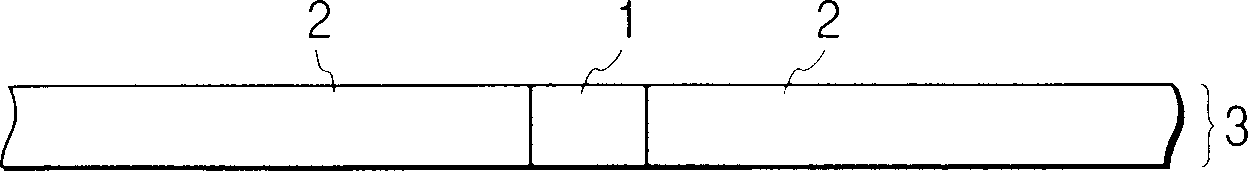
[0088] Depend on Figures 1A to 1H A crystalline silicon thin film formed by the method shown in is described as Example 1 of the present invention.
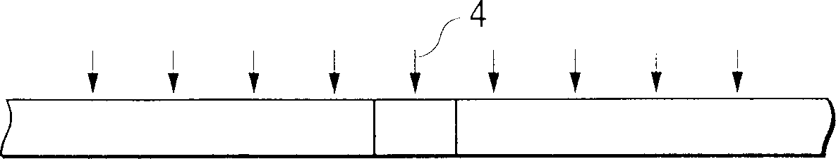
[0089] An amorphous silicon film containing crystalline silicon clusters was formed to a thickness of 50 nm by vapor deposition on a substrate composed of silicon dioxide and other components and having an amorphous surface. This amorphous silicon film containing crystalline silicon clusters was irradiated with an energy beam from the surface side (locally excluding a small area of 1 μm diameter), thereby partially amorphizing the crystalline silicon clusters in the irradiated area of the film. The obtained film was used as a starting film.
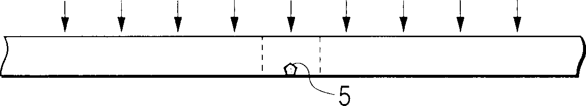
[0090] This initial film was treated with a KrF excimer laser beam at approximately 200 mJ / cm 2 The energy density is irradiated for 30 nanoseconds to melt and resolidify to obtain a crystal thin film.
[0091] The crystal grain shape of the formed crystal thin film was examined. As...
Embodiment 2
[0095] Depend on Figures 1A to 1H Another crystalline silicon thin film formed by the method shown in is described as Example 2 of the present invention.
[0096] In the same manner as in Example 1, an amorphous silicon film containing crystalline silicon clusters was formed to a thickness of 50 nm by vapor deposition on a substrate mainly composed of silicon dioxide and having an amorphous surface. This amorphous silicon thin film containing crystalline silicon clusters was irradiated with an energy beam from the surface side (partially excluding a small area of 0.7 µm in diameter), thereby obtaining a starting thin film. In this example, unlike Example 1, the crystalline silicon clusters contained in the thin film become completely amorphous in the region where the energy beam is irradiated.
[0097] This starting film was treated with an ArF excimer laser beam at approximately 210 mJ / cm 2 The energy density is irradiated for 30 nanoseconds to melt and resolidify to obt...
Embodiment 3
[0102] Depend on Figures 1A to 1H The third crystalline silicon film formed by the method shown in
[0103] Embodiment 3 is described.
[0104] A polysilicon film having a thickness of 80 nm was formed as a starting film on a substrate having an amorphous surface composed of an inorganic silicon compound by vapor deposition. Deposition of the initial film by means of selective deposition, at about 2 μm 2 Average diameters of about 300 nm were obtained in small regions of , and about 100 nm in other regions in the plane of the film.
[0105] This starting film was treated with a XeCl excimer laser beam at approximately 300 mJ / cm 2 The energy density is irradiated for 40 nanoseconds to melt and resolidify to obtain a crystal thin film.
[0106] The crystal grain shape of the formed crystal thin film was examined. found that single grains have been centered at about 2µm 2 The above-mentioned small regions grow around to a particle size of about 3 μm in diameter. The surro...
PUM
| Property | Measurement | Unit |
|---|---|---|
| thickness | aaaaa | aaaaa |
| diameter | aaaaa | aaaaa |
| diameter | aaaaa | aaaaa |
Abstract
Description
Claims
Application Information
 - R&D
- Intellectual Property
- Life Sciences
- Materials
- Tech Scout
- Unparalleled Data Quality
- Higher Quality Content
- 60% Fewer Hallucinations
Browse by: Latest US Patents, China's latest patents, Technical Efficacy Thesaurus, Application Domain, Technology Topic, Popular Technical Reports.
© 2025 PatSnap. All rights reserved.Legal|Privacy policy|Modern Slavery Act Transparency Statement|Sitemap|About US| Contact US: help@patsnap.com