
Afterheat recovering device of I.C. engine

A technology of waste heat recovery device and internal combustion engine, which is applied to internal combustion piston engines, combustion engines, mechanical equipment, etc., can solve the problems of long time and inefficient recovery of condensation heat, and achieve the effect of avoiding contact and not easy to deteriorate

Inactive Publication Date: 2002-12-04
HONDA MOTOR CO LTD
View PDF2 Cites 4 Cited by
  • Summary
  • Abstract
  • Description
  • Claims
  • Application Information

AI Technical Summary

Problems solved by technology

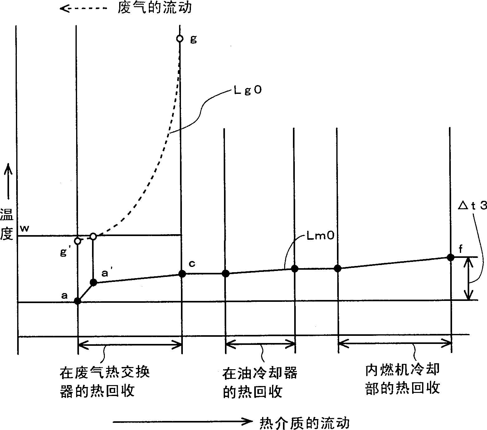
Therefore, the temperature of the introduced heat medium cannot be said to be sufficiently lower than the dew point W, so it takes a long time for the exhaust gas to reach the dew point W, and as a result, the heat of condensation cannot be recovered with sufficient efficiency.
If the temperature of the exhaust gas can drop below the dew point W in the early stage, more heat of condensation can be recovered, but this problem has not been solved in the past

Method used


Image

  • Afterheat recovering device of I.C. engine
  • Afterheat recovering device of I.C. engine
  • Afterheat recovering device of I.C. engine

Examples


Embodiment Construction

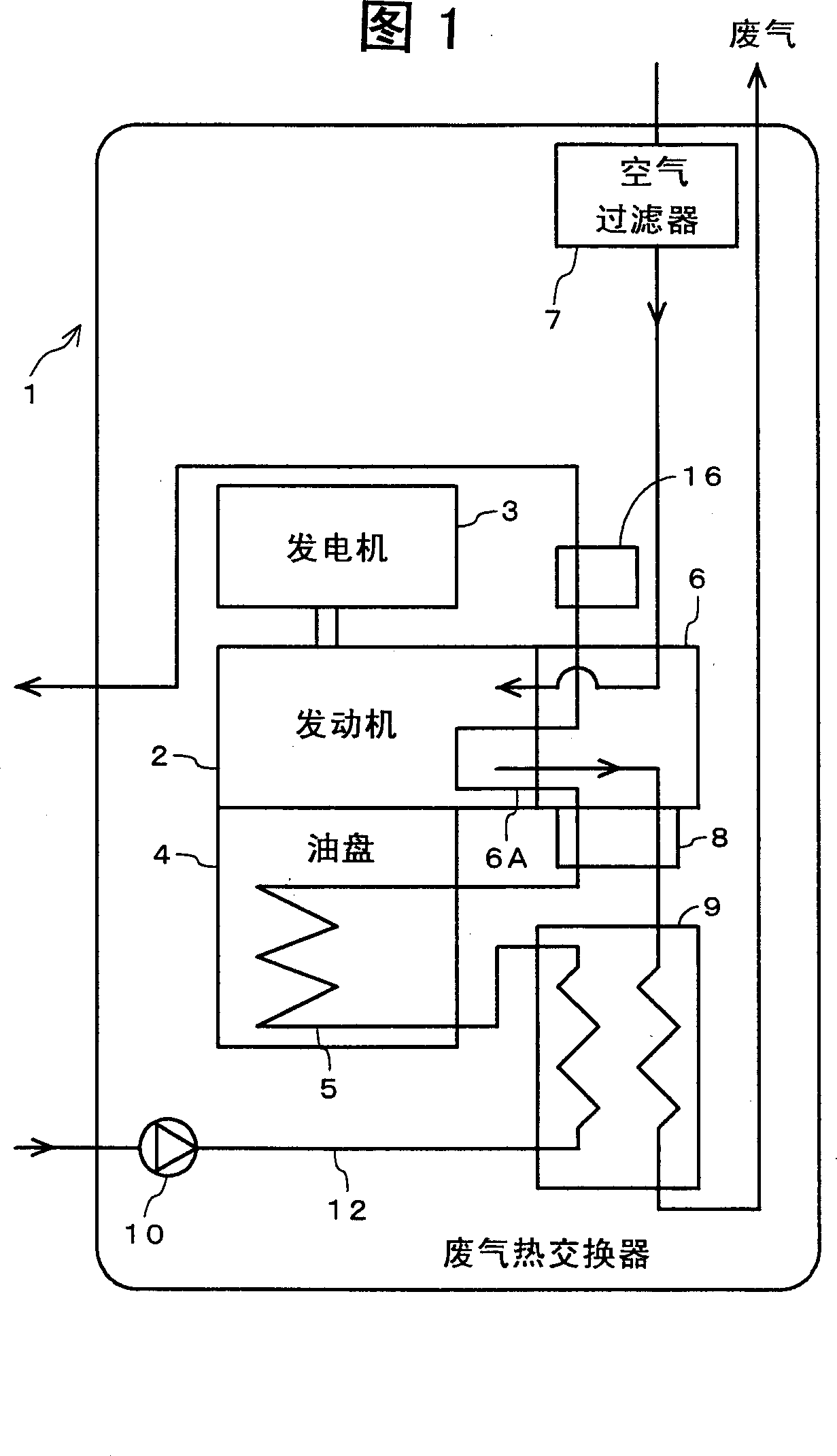
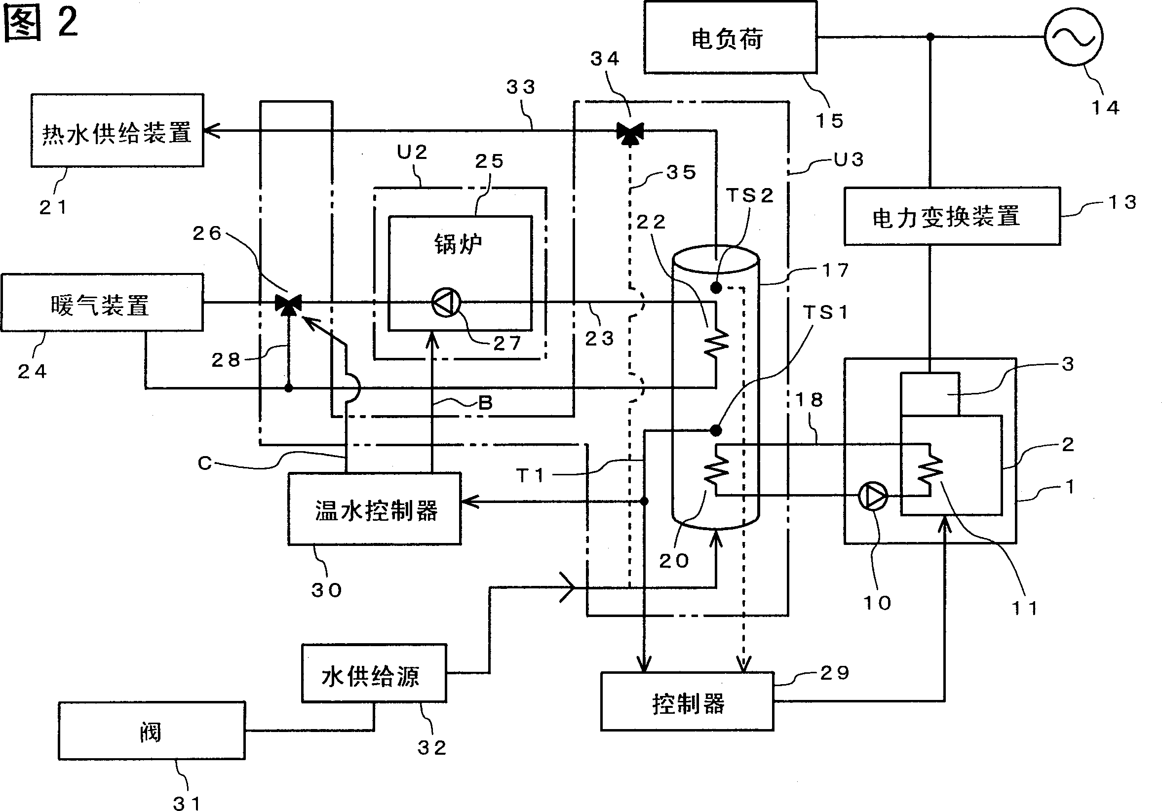
[0025] An embodiment of the present invention will be described in detail below with reference to the accompanying drawings. As shown in FIG. 1 , a waste heat recovery device 1 included in a cogeneration device is configured to recover waste heat from an internal combustion engine portion of an internal combustion engine generator. An internal combustion engine 2 and a generator 3 mechanically connected to the internal combustion engine 2 are provided in the waste heat recovery device 1 . The generator 3 generates alternating current corresponding to the rotational speed of the internal combustion engine. The internal combustion engine 2 is provided with an oil pan 4 storing lubricating oil. An oil cooler (oil heat exchanger) 5 is connected to the oil pan 4, and the oil heat exchanger 5 performs heat exchange between oil in the oil pan 4 and a heat medium (cooling water). The cylinder head 6 of the internal combustion engine 2 takes in air from an air filter 7 . Exhaust gas...


PUM


Abstract

Provided is a waste heat recovery device of an internal combustion engine. A circulation path (12) for circulating a heat medium in a cooling unit (6A) of an internal combustion engine (2) and an exhaust gas heat exchanger (9) utilizing exhaust gas of the internal combustion engine (2) is provided. The output side of the circulation path (12) is connected to an output heat exchanger provided in a hot water storage tank or the like. The heat medium introduced by the pump (10) circulates through the exhaust gas heat exchanger (9), the oil heat exchanger (5), and the water jacket (cooling part) (6A) in sequence, and then is output. The heat medium introduced into the exhaust gas heat exchanger (9) is set at a low temperature such that the water vapor in the exhaust gas is lower than its dew point by adjusting the flow rate or the like. The heat medium recovers the heat of the exhaust gas and the condensation heat of the exhaust gas, and guides it to the cooling unit (6A) to further raise the temperature. In this way, the waste heat of the internal combustion engine is effectively recovered.

Description

technical field [0001] The invention relates to a waste heat recovery device of an internal combustion engine, in particular to a waste heat recovery device of an internal combustion engine used as a power source of a cogeneration device and the like. Background technique [0002] In recent years, the need to consider the issue of environmental protection of the earth has increased, and in order to effectively use energy, technologies that recycle heat generated during operation, such as combined heat and power plants, have been receiving more and more attention. In this cogeneration device, since the temperature of the exhaust gas is higher than that of the high-temperature part of the main body of the internal combustion engine used as the power source, when recovering the waste heat, the heat recovery medium (generally, the cooling water of the internal combustion engine) is introduced into the cooling water of the internal combustion engine. The part recovers the heat, a...

Claims


Application Information

Patent Timeline
Patent Type & Authority Applications(China)
IPC IPC(8): F02G5/04F02G5/02F24H1/00
CPCF02G5/02Y02E20/14Y10S165/916Y10S165/921Y02T10/12
Inventor 户川一宏竹村一仁
Owner HONDA MOTOR CO LTD
Learn More