


Quick Research
Generate reliable direction feasibility study reports for your R&D in just a few steps.

Technical Q&A
Discover and master advanced knowledge NOW. Basics, ideas, possibilities, all at once.

Find Solutions
As an expert in R&D theories, this can generate solutions to your technical problems instantly.

Evaluate Feasibility
Analyze your overall solution with one click, know your potential R&D risks in advance.

Monitor Landscape
Get weekly tech updates, stay abreast of the latest tech innovations and key insights.
Characterization system for property measurement of intermediate infrared waveband semiconductor laser
An infrared band and measurement system technology is applied in the field of performance measurement and characterization of semiconductor lasers in the mid-infrared band. high precision effect
- Summary
- Abstract
- Description
- Claims
- Application Information
AI Technical Summary
Problems solved by technology
Method used
Image

Examples
Embodiment 1
[0032] Example 1 Measurement of 2μm band AlGaAsSb / InGaAsSb multi-quantum well laser
[0033] 1. First place the laser chip on the microprobe test bench controlled by thermoelectric cooling, and directly add the driving current with the microprobe (in this embodiment, the laser is a ridge waveguide type, the waveguide width is 2.5 μm, and the cavity length is 700 μm) .
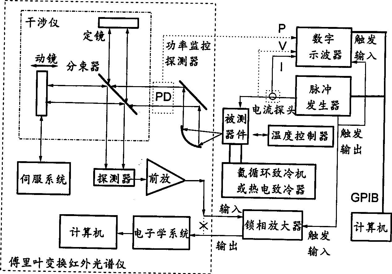
[0034] 2. Connect each hardware device according to the system block diagram. Inject liquid nitrogen into the InSb detector for cooling.
[0035] 3. Turn on the power of the computer, digital oscilloscope, pulse signal generator, FTIR spectrometer, lock-in amplifier, heat sink temperature controller and other equipment.
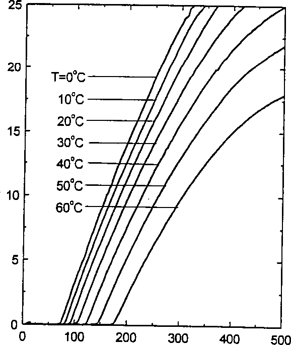
[0036] 4. Adjust the temperature of the heat sink to the required temperature (0-60°C in this embodiment, step by 10°C).
[0037] 5. Run the system control software on the computer to initialize the experimental conditions (that is, set the pulse width, period, measurement parameters of the...
Embodiment 2
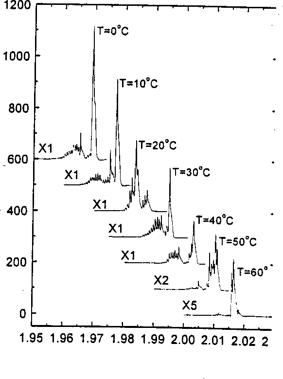
[0041] 9, fixed drive condition (in the present embodiment, drive current is 200mA, and pulse width is 1 μ s, and cycle is 100KHz), and the lasing spectrum under each condition is recorded by FTIR spectrometer as follows image 3 . Example 2 Measurement of 8 μm band InAlAs / InGaAs / InP quantum cascade laser
[0042] 1. Install the packaged laser chip on the cold head of the helium compression cycle refrigerator, connect the drive line, seal the outer cavity and evacuate it, and start cooling.
[0043] 2. Connect each hardware device according to the system block diagram. Inject liquid nitrogen into the HgcdI detector for cooling.
[0044] 3. Turn on the power of the computer, digital oscilloscope, pulse signal generator, FTIR spectrometer, lock-in amplifier, heat sink temperature controller and other equipment.
[0045] 4. Adjust the temperature of the heat sink to the desired temperature (20-200K in steps of 30K in the embodiment).
[0046] 5. Run the system control softwar...
PUM
 Abstract
Description
Claims
Application Information
 - R&D Engineer
- R&D Manager
- IP Professional
- Industry Leading Data Capabilities
- Powerful AI technology
- Patent DNA Extraction
Browse by: Latest US Patents, China's latest patents, Technical Efficacy Thesaurus, Application Domain, Technology Topic, Popular Technical Reports.
© 2024 PatSnap. All rights reserved.Legal|Privacy policy|Modern Slavery Act Transparency Statement|Sitemap|About US| Contact US: help@patsnap.com