
Compact micro-wave antenna

An antenna and microwave technology, applied in the high-frequency and microwave range, printed circuit board and mobile communication equipment, can solve the problems of impossible electrical adaptation, rare and expensive conductor track, and achieve the adjustment of position and distance, production Simple, flexible and adjustable effects

Inactive Publication Date: 2002-05-15
KONINK PHILIPS ELECTRONICS NV
View PDF1 Cites 3 Cited by
  • Summary
  • Abstract
  • Description
  • Claims
  • Application Information

AI Technical Summary

Problems solved by technology

However, these antennas have the disadvantage that at least part of the conductor tracks run inside the substrate, and thus the substrate will be produced in several layers to have minimum dimensions, which may be relatively expensive
Furthermore, such an arrangement of the conductor tracks would not allow an electrical adaptation of the conductor tracks to the specific structural form in the finished state, since the conductor tracks are difficult to reach or only partially accessible

Method used


Image

  • Compact micro-wave antenna
  • Compact micro-wave antenna
  • Compact micro-wave antenna

Examples


no. 1 example

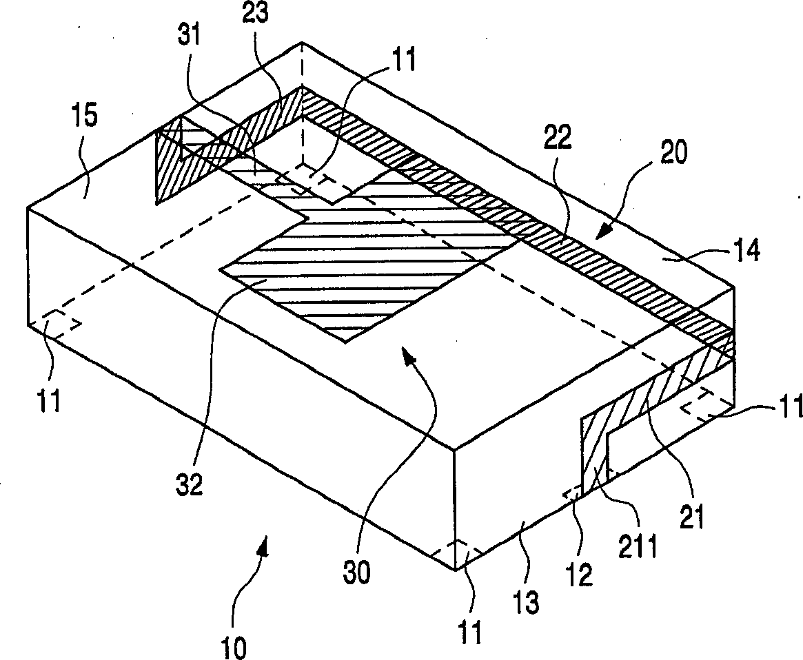
[0020] figure 1 A first embodiment of the invention is schematically shown;

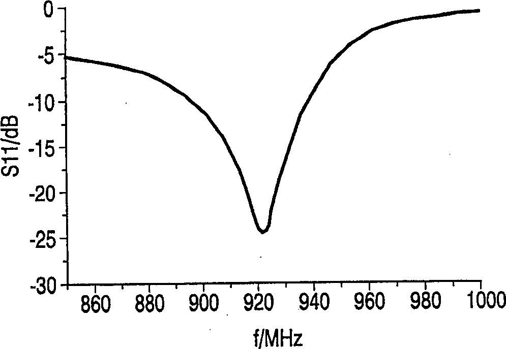
[0021] figure 2 The impedance range measured for this example is shown;

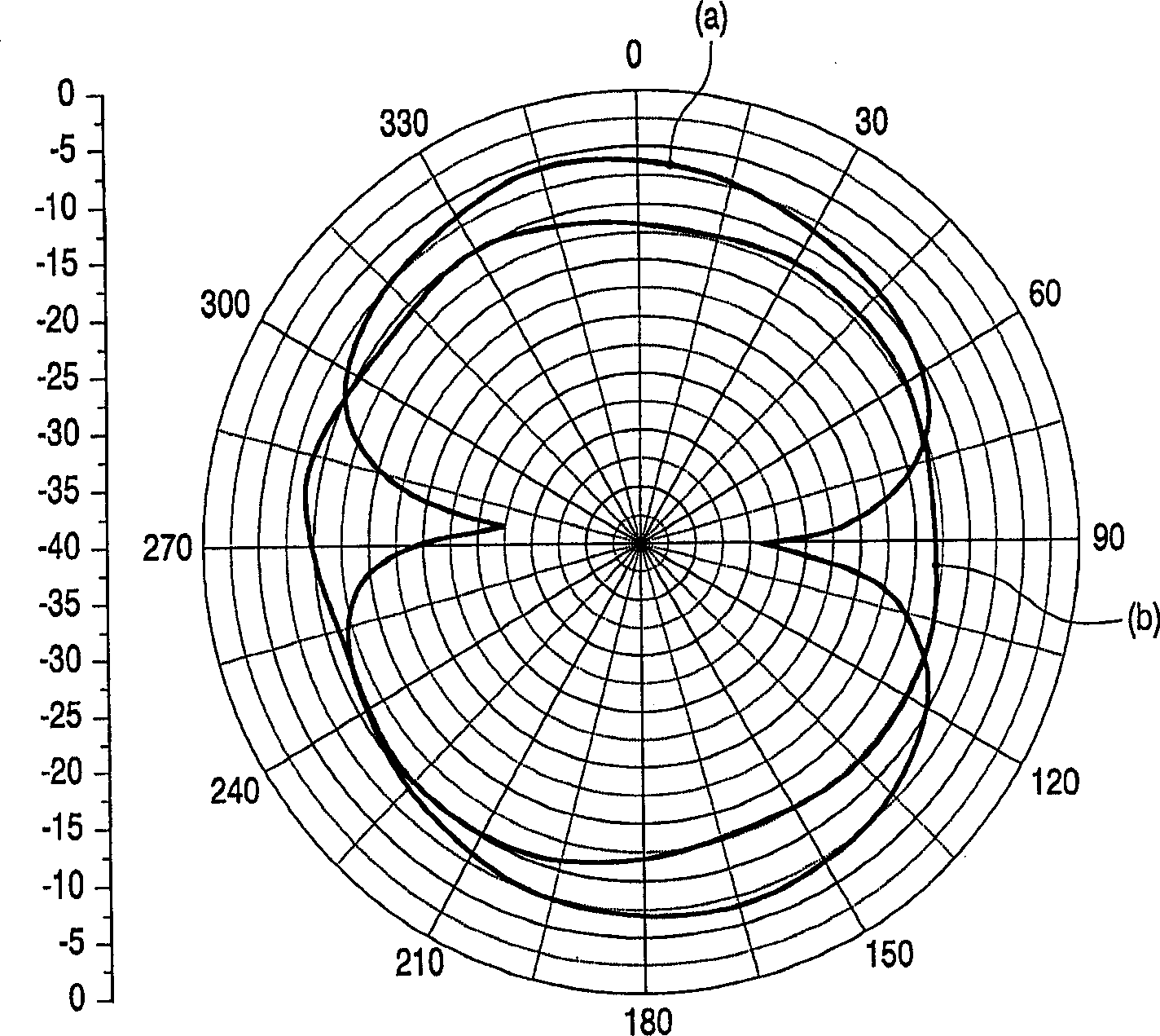
[0022] image 3 shows the directional properties measured for this example;

[0023] Figure 4 shows a second embodiment of the invention;

[0024] Figure 5 shows the range of impedances measured for this example; and

[0025] Figure 6 A printed circuit board with an antenna according to the invention is shown.

[0026] Examples

[0027] The embodiment described below comprises a substrate composed of substantially rectangular blocks, the height of which is smaller than its length and width by a factor of about 3 to 10. Thus, in the following description will be referred to as the upper and lower (larger) surfaces of the substrate, as shown in the figures as a first upper surface and a second lower surface, while the surface perpendicular thereto will be indicated as a second surface. One to the fourth side.

[002...


PUM


Abstract

A miniaturized antenna is described with at least a ceramic substrate (10) and a metallization, particularly designed for use in the high-frequency and microwave ranges. The antenna is characterized in that the metallization is a surface metallization which is formed by a feed terminal (12) for electromagnetic energy to be radiated, by at least a first metallization structure (30), and by a conductor track (20) extending along at least part of the circumference of the substrate (10), which track connects the feed terminal to the at least one first metallization structure (30), which first metallization structure (30) comprises a first conductor track portion (31) extending from a side of the substrate lying opposite the feed terminal (12) towards the feed terminal and a first metallization pad (32). The antenna can be provided on a printed circuit board by means of surface mounting and has a great impedance and radiation bandwidth, so that it is particularly suitable for use in mobile telephones operating in the GSM and UMTS bands.

Description

technical field [0001] The invention relates to a miniaturized microwave antenna having at least a ceramic substrate and a metal, especially for high-frequency and microwave ranges. The invention further relates to a printed circuit board and a mobile communication device with such an antenna. Background technique [0002] Following the trend towards ever smaller miniaturization of electronic components, especially in the field of communication technology, all producers of passive and / or active components are concentrating their activities in this area. The use of electronic components, in particular in the field of high-frequency and microwave technology, however, poses specific problems, since many properties of electronic components depend on their physical size. From the generally known fact that the wavelength of the signal becomes smaller with increasing frequency, this again has the consequence that reflections especially affect the provision of the signal source. ...

Claims


Application Information

Patent Timeline
Patent Type & Authority Applications(China)
IPC IPC(8): H05B6/72H01Q1/24H01Q1/36H01Q1/38H01Q5/357H01Q5/40H01Q9/04H01Q9/30H01Q9/40H01Q13/08
CPCH01Q9/045H01Q1/243H01Q5/0072H01Q5/0051H01Q1/38H01Q21/30H01Q5/357H01Q5/40H01Q13/08
Inventor A·希尔格斯
Owner KONINK PHILIPS ELECTRONICS NV
Learn More