Light IP exchange route structure

A technology of routers and optical switches, applied in the field of optical network systems, can solve the problems that electronic buffers cannot provide end-to-end transparent optical paths for data packet switching, so as to improve flexibility and throughput, reduce physical size, and reduce component requirements Effect

Inactive Publication Date: 2002-01-23
ALCATEL LUCENT SAS
View PDF0 Cites 7 Cited by
  • Summary
  • Abstract
  • Description
  • Claims
  • Application Information

AI Technical Summary

Problems solved by technology

Electronic buffers cannot provide an end-to-end transparent optical path for data packet switching

Method used


Image

  • Light IP exchange route structure
  • Light IP exchange route structure
  • Light IP exchange route structure

Examples


Embodiment Construction

[0030] The preferred embodiment of the invention is illustrated in the drawings, like numerals being used to designate like and corresponding elements in the various drawings.

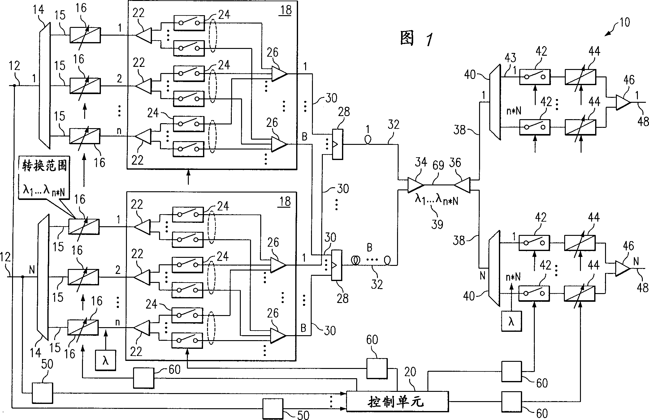
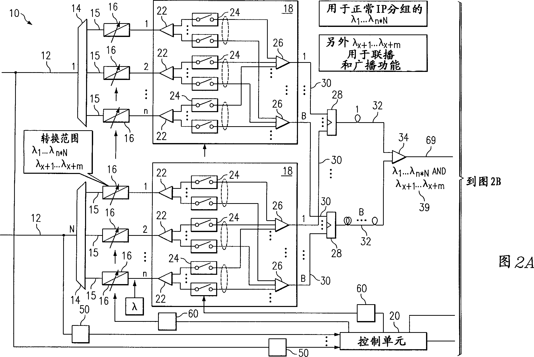
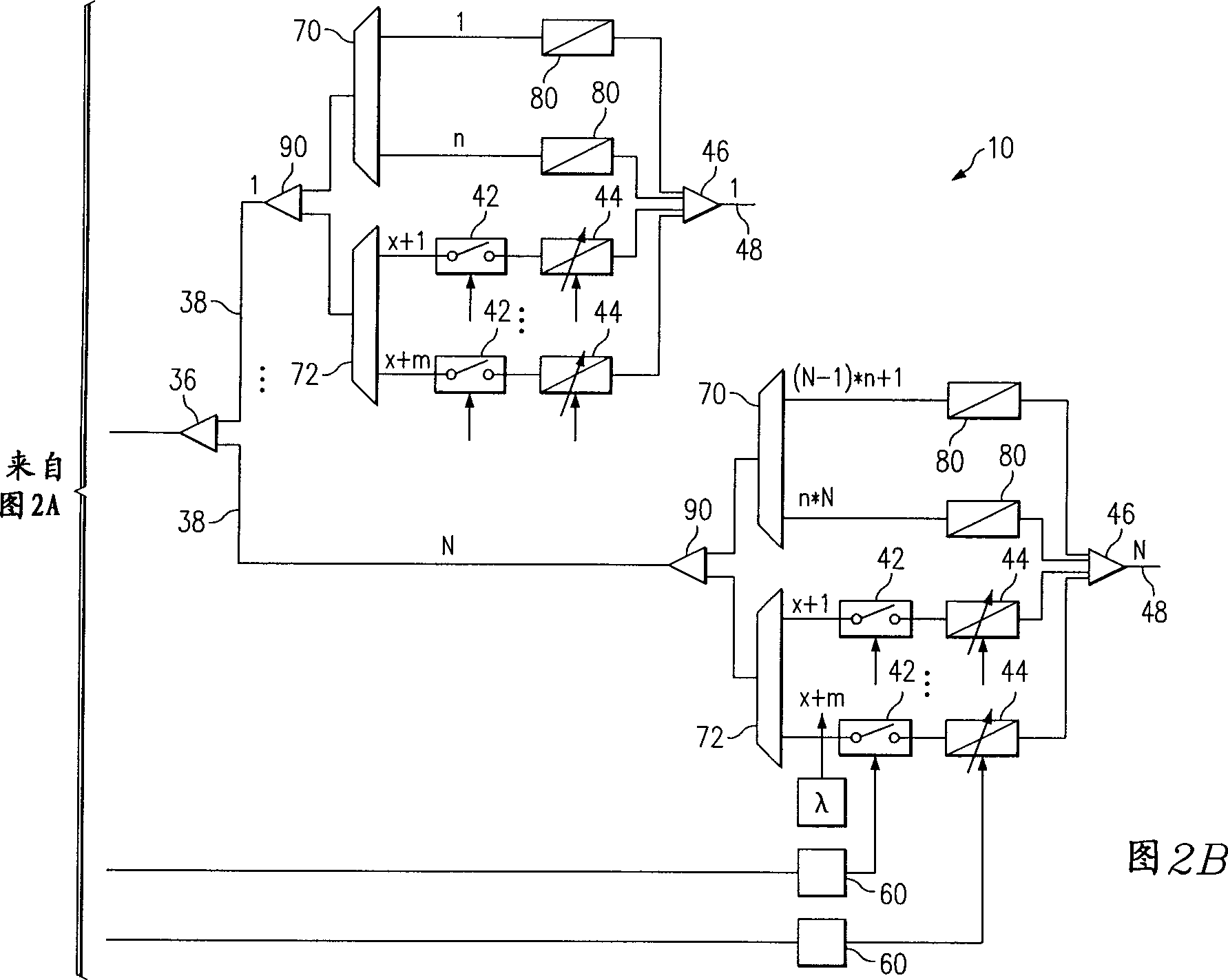
[0031] FIG. 1 shows an embodiment of the structure of an optical IP switching router for IP data packet switching according to the present invention. Optical switch 10 has 1 to N input WDM fibers 12, where N is any number whose value is limited only by size and technology constraints, as described in more detail below. The input WDM fiber 12 can carry data packets consisting of optical payload data bits and data packet header information. The header information can be extracted and electronically processed by the control unit 20 . The remainder of the data packet may pass through the optical switch 10 in full optical form and output from the optical switch 10 to one of the N output WDM fibers 48 . Control unit 20 may direct the various elements of optical switch 10 to ensure that IP data packets are ...


PUM


Abstract

An optical Internet Protocol switching method and system are disclosed for switching data packets entirely in the optical domain. The method of the present invention includes the steps of receiving a plurality of data packets at an optical switch and extracting the header information for each data packet for processing at a control unit. The data packets can be demultiplexed at a plurality of demultiplexers and each data packet assigned a different internal wavelength. The method of the present invention can route each data packet to one or more delay buffers based on a current output status. The data packets can be combined into a single output from the delay buffers and broadcast to a plurality of outputs channels. The method of the present invention can select one or more data packets to output through at least one of the output channels and can convert the assigned internal wavelengths of the selected data packets to their original wavelength using a tunable wavelength converter. The selected data packets can be multiplexed together for transmission on an output Wave Division Multiplexing ('WDM') fiber.

Description

technical field [0001] The present invention relates generally to optical networking systems and methods, and more particularly to systems and methods for improved optical Internet Protocol (IP) switching router architectures. Background technique [0002] Data traffic on the network, especially on the Internet, has increased significantly in the past few years, and this trend will continue with the introduction of new services that require greater bandwidth. The significant increase in Internet Protocol (IP) traffic has resulted in the equipment line and IP router capacity in corporate networks not being able to keep up with the need for greater bandwidth. A large amount of Internet traffic requires networks with high-capacity switching routers capable of routing data packets of various lengths and bursts. [0003] It will become difficult, if not impossible, for current electronic IP switching routers to scale with the increase in IP traffic. Optical packet switching rou...

Claims


Application Information

Patent Timeline
IPC IPC(8): H04L12/18H04L12/56H04Q11/00
CPCH04Q2011/0039H04L12/56H04Q2011/0015H04Q11/0066H04Q2011/0011H04Q2011/0047H04Q2011/002H04Q11/0005H04Q2011/0024H04Q2011/0016
Inventor 葛安(音译)拉克施曼·S.·塔米尔
Owner ALCATEL LUCENT SAS
Why Eureka
Try Eureka