Stator bonding nib

A stator, pointed wedge technology, applied in the direction of structural connection, connection with grounding device, manufacture of stator/rotor body, etc.

Inactive Publication Date: 2001-04-04
GENERAL ELECTRIC CO
View PDF0 Cites 0 Cited by
  • Summary
  • Abstract
  • Description
  • Claims
  • Application Information

AI Technical Summary

Problems solved by technology

However, as casing coatings and processing methods have improved to achieve the required corrosion

Method used


Image

  • Stator bonding nib
  • Stator bonding nib
  • Stator bonding nib

Examples


Example Embodiment

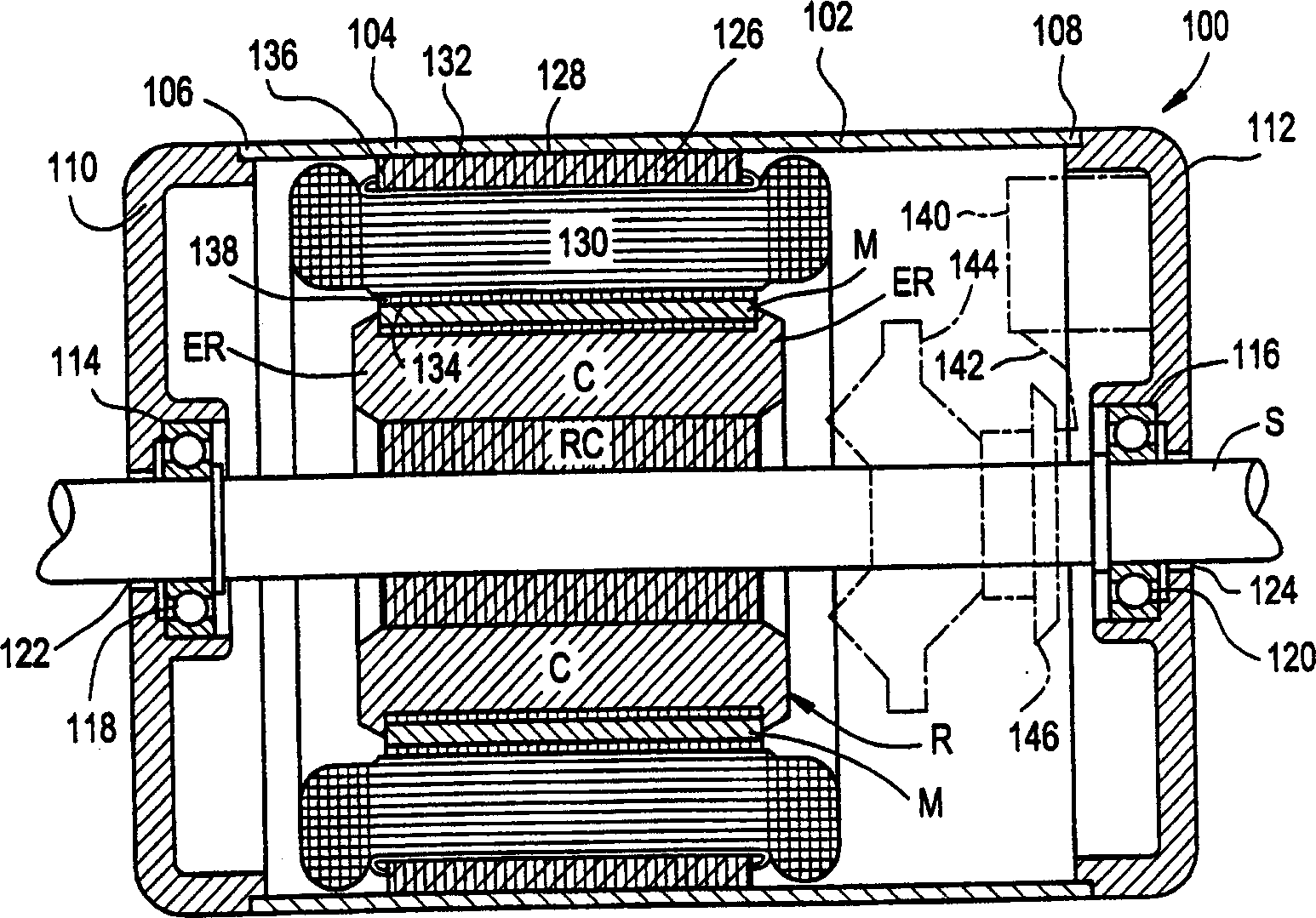
[0014] figure 1 It is a schematic diagram of an exemplary motor including a housing 102 with a housing 104 with second ends 106,108. Although the stator laminations are referred to as electric motor laminations in this article, it should be understood that the present invention is not limited to be implemented with any specific motor. The invention can be used for other motors.

[0015] The housing 104 includes a protective coating, which reduces the possibility of corrosion of the housing 104. In one embodiment, the protective coating is a paint that substantially covers the entire surface of the housing 104. An exemplary coating is a mixture of #CR-648Powercron resin and #CP-583Powercron, available from PPG Industries, P. O. Box 127, Springdale, Pennsylvania 15144. The first end shield 110 is connected to the end 106, and the second end shield 112 is connected to the end 108. The end shields 110, 112 contain the support portions 114, 116 of the bearing assemblies 118, 120. The...


PUM


Abstract

A stator (126) includes projecting portions (132) extending from an outer edge (154) of a plurality of stator laminations (148). The projecting portions (132) form a point (158). When the stator is inserted into a motor housing (102), the projecting portions scrape along an inner surface of the housing (102). The contact between the projecting portions and the housing (102) achieves a bond between the stator (126) and the housing (102).

Description

Background of the invention [0001] The present invention relates generally to electrical machines, and more particularly to connection wedges extending from the stator of an electrical machine. [0002] Electric machines, such as electric motor generators, generally include a housing, a stator, and a rotor assembly. The housing includes an outer shell having a protective coating and two end caps, and houses at least a portion of the rotor assembly. The stator generally includes a core of magnetic material having an axially extending bore for receiving the rotor assembly. The rotor assembly includes a rotor core and a rotor shaft extending through the core. The rotor assembly passes through the stator bore and the two end shields. [0003] The stator core generally consists of a number of identical laminations coated with insulating material aligned and arranged in a stack held together by clips and an interlocking tab. Each lamination includes a number of teeth extending r...

Claims


Application Information

Patent Timeline
IPC IPC(8): H02K1/00H02K1/04H02K1/16H02K1/18H02K15/02
CPCY10T29/49009H02K1/185H02K11/0089Y10T29/49078H02K11/40H02K15/02
Inventor T·W·卡雷E·L·坎贝尔J·C·迪尔斯
Owner GENERAL ELECTRIC CO
Why Eureka
Try Eureka