
Overlapped light waveguide 3-D data memory able to even readout and data recording method

A three-dimensional data and data recording technology, which is applied in data recording, digital memory information, static memory, etc., can solve the problem of microcrystalline and microbubble materials being deformed after being placed for a long time, difficult to accurately control the size and distribution of microbubbles, and storage energy The use of problems such as unreasonable use can achieve the effect of being conducive to large-scale production, long-term data storage, and not easy to deform

Inactive Publication Date: 2006-11-08
NANJING UNIV OF POSTS & TELECOMM
View PDF2 Cites 0 Cited by
  • Summary
  • Abstract
  • Description
  • Claims
  • Application Information

AI Technical Summary

Problems solved by technology

Its disadvantages are similar to those of microcrystalline composites, and the size and distribution of microbubbles are not easy to precisely control
Not only that, the recorded information is not easy to preserve for a long time, and the microcrystalline and microbubble materials will be deformed after being placed for a long time, which will affect the correct reading of the information
If the double-beam recording method is used, there will inevitably be a data erasure effect (that is, the readout light will affect the original recorded information)
These factors will affect the lifetime of the entire memory device
[0006] Again, the memory energy utilization is not reasonable enough
After the addressing light is coupled into the waveguide from the side, sometimes its light intensity has been attenuated to close to zero before reaching the end of the waveguide, and the data at the end of the waveguide cannot be read at this time.
And sometimes most of the addressing light energy is transmitted from the end of the waveguide instead of being scattered by the information symbol, so the energy utilization efficiency is not high, and the scattered light emitted is very weak

Method used


Image

  • Overlapped light waveguide 3-D data memory able to even readout and data recording method
  • Overlapped light waveguide 3-D data memory able to even readout and data recording method
  • Overlapped light waveguide 3-D data memory able to even readout and data recording method

Examples


Embodiment Construction

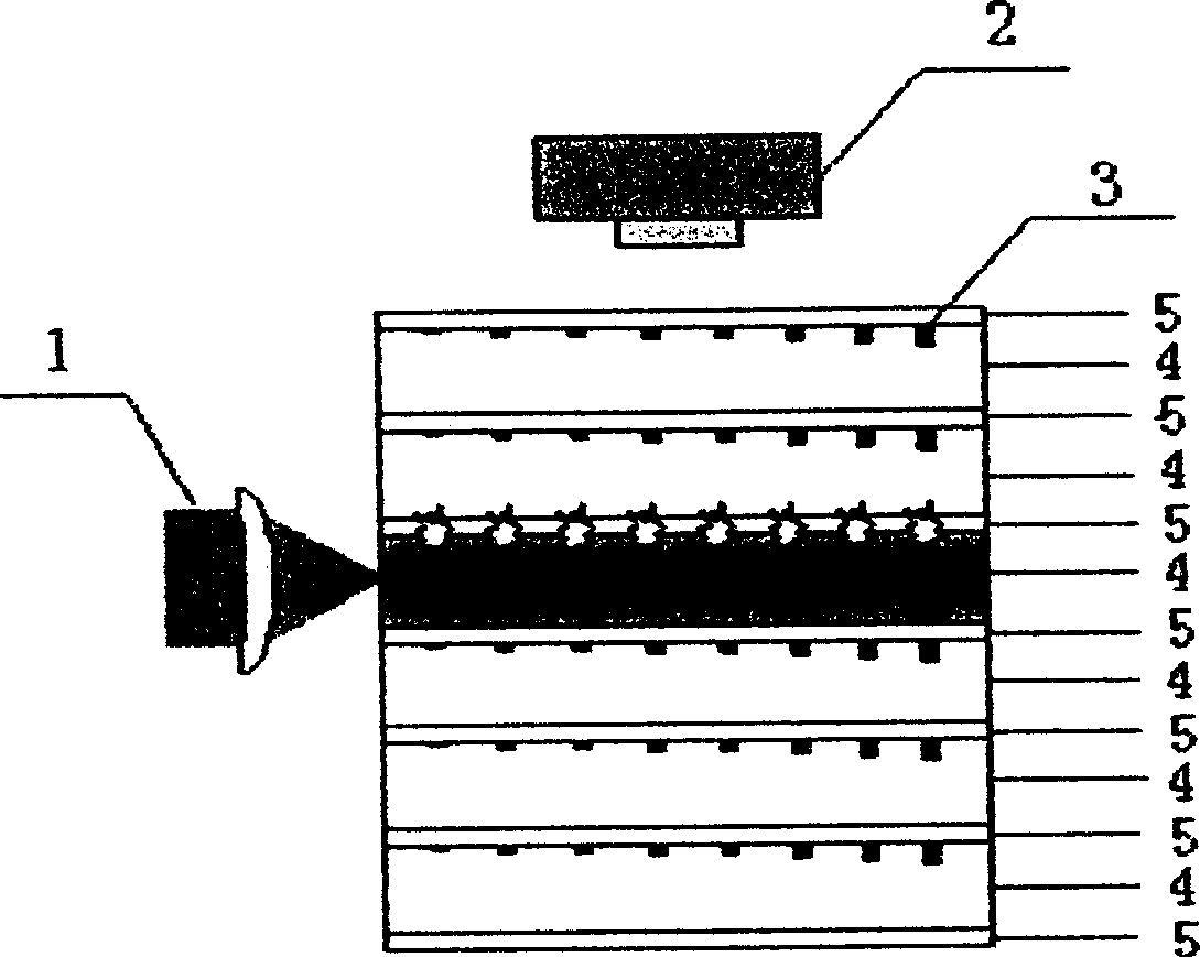
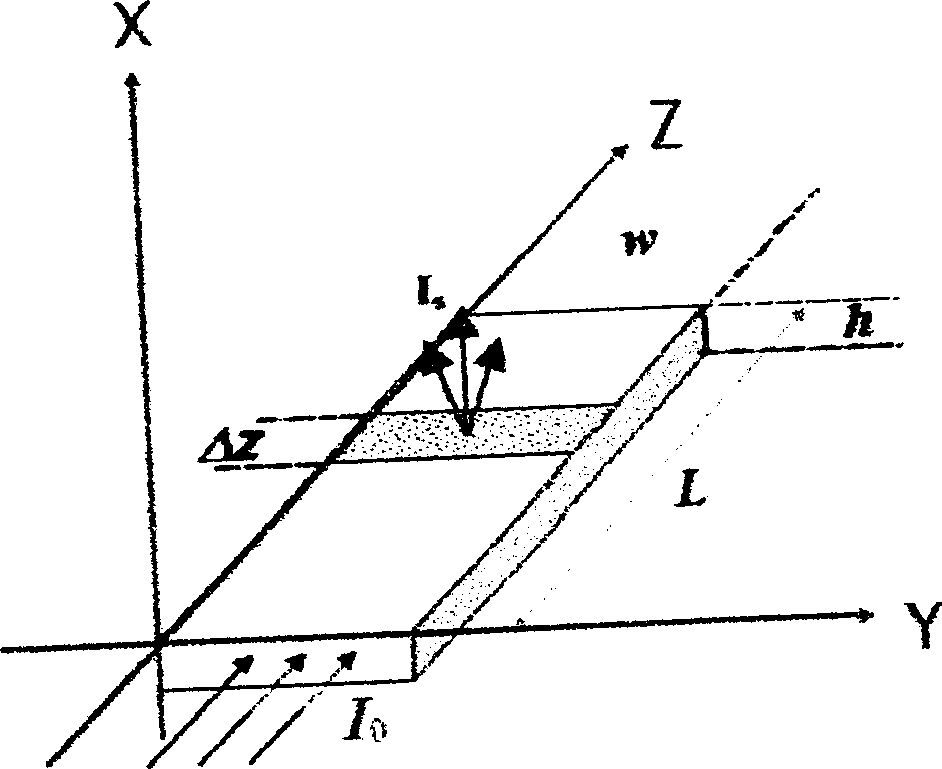
[0049] The structure of the uniform read-out stacked optical waveguide three-dimensional data memory of the present invention is as follows: the information layer 4 is covered with a cladding layer 5 to form an optical structure thin film unit, and then the optical structure composed of the information layer 4 and the cladding layer 5 is stacked up and down. In this way, the information layer 4 and the two adjacent cladding layers 5 form a complete waveguide structure; information symbols 3 with different depths are arranged on the surface of the information layer 4, and the depth of the information symbols 3 varies with the addressing light. The propagation direction is gradually deepened, and thus combined into a uniformly read stacked optical waveguide three-dimensional data memory. The information layer 4, the cladding layer 5 and the information symbol 3 are all made of polymer transparent materials, and the refractive index n of the information layer 4 is 1 greater than ...


PUM


Abstract

Structure of data storage is as following: a cladding layer covered on an information layer constitutes an optical structured thin film unit. Then, superposed information layers and cladding layers in upper and lower direction constitute thin film unit. Since refractive index of information layer is larger than refractive index of cladding layer, thus, an information layer and two adjacent cladding layers form an integrated waveguiding structure. Information symbols in different depths are setup on surface of information, and depths of information symbols are deepened gradually along propagation direction of addressing light so as to form 3D data storage readable by laminated light waveguides evenly. Mould pressing method is adopted in recording method. Grooves in different depths are pressed on surface of information layer directly by using mould. Polymer is filled to grooves so as to produce information symbols. Adhesion agent is selected as material of cladding layers.

Description

technical field [0001] The invention relates to an optical storage device and a data recording method thereof, belonging to the technical field of optical information storage. Background technique [0002] The laminated optical waveguide three-dimensional data memory and its data recording and reading method is an optical information storage technology, specifically related to the method of realizing three-dimensional recording and reading of data information by using a multi-layer planar optical waveguide structure. The laminated waveguide memory is composed of multiple The planar optical waveguide is stacked, and each waveguide is composed of a recording layer, a core layer and a cladding layer. The recording layer of the waveguide is a photosensitive medium, which is used as a recording layer to store data; the core layer is a non-photosensitive medium, which is used as an address layer. , used to guide the addressing beam; the cladding layer is ...

Claims


Application Information

Patent Timeline
Patent Type & Authority Patents(China)
IPC IPC(8): G11B7/24G11B7/005G11C13/04G11B7/24038
Inventor 杨涛蔡祥宝
Owner NANJING UNIV OF POSTS & TELECOMM
Learn More