Catalytic oxidation-bioreactor waste gas treatment apparatus
A technology of waste gas treatment equipment and bioreactor, which is applied in the direction of chemical instruments and methods, air quality improvement, separation methods, etc., to achieve the effect of maintaining stable gas concentration, reducing auxiliary equipment, and improving purification efficiency
- Summary
- Abstract
- Description
- Claims
- Application Information
AI Technical Summary
Problems solved by technology
Method used
Image
Examples
Embodiment 1
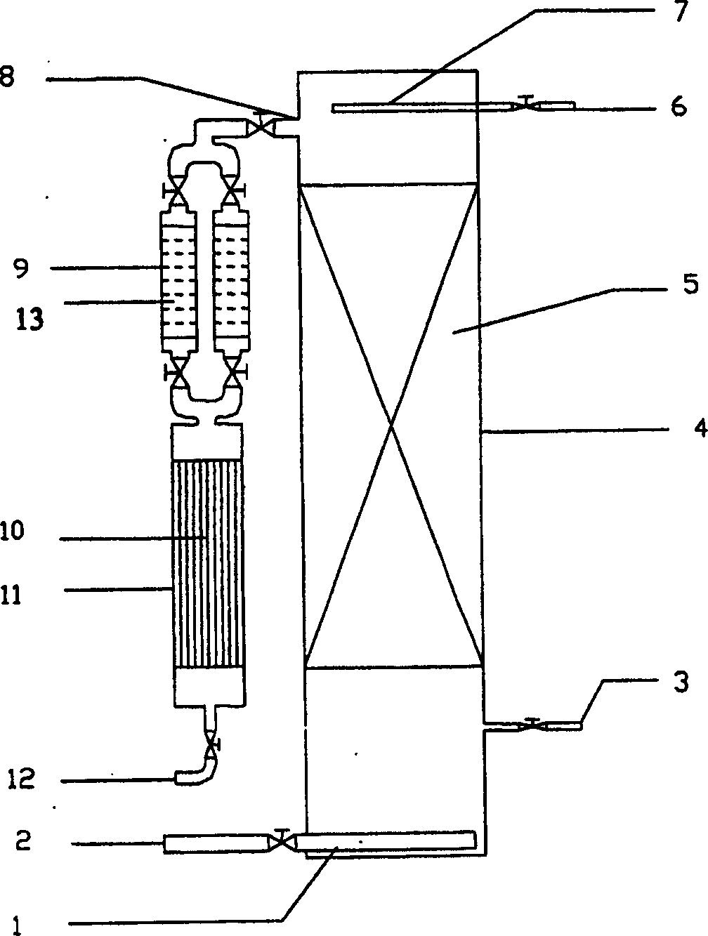
[0035] See figure 1 .
[0036] Catalytic oxidation-bioreactor exhaust gas treatment equipment made of plastic plates, its length, width and height are 50cm, 50cm, 1500cm respectively, including bioreactor 4 with packing, catalytic oxidizer 11, etc.; Bioreactor 4, equipped with oxidation catalyst 10% Cu / Al 2 o 3 The catalytic oxidizer 11 and the drier 9 that desiccant 13 is housed constitute;
[0037] An air inlet 2 is opened on the lower side wall of the bioreactor 4, and a perforated pipe 1 is installed at the air inlet 2. The other side wall of the lower part is provided with a water outlet 3, the air inlet 2 should be lower than the water outlet 3, and the upper side wall is provided with a spray liquid inlet 6, and there is a perforated pipe 7 at the inlet 6;
[0038] The interior of the bioreactor 4 is filled with fillers 5 such as sponge or perlite, and the other side wall of the upper part is provided with an air outlet pipe 8, which is connected to a dryer 9;
[0...
Embodiment 2
[0046] See figure 1 .
[0047] Catalytic oxidation-bioreactor exhaust gas treatment equipment made of plexiglass, its diameter is 10cm, including bioreactor 4, catalytic oxidizer 11 etc. with filler 5; Catalyst 10% Cu / TiO 2 The catalytic oxidizer 11 and the drier 9 that desiccant 13 is housed constitute;
[0048] An air inlet 2 is opened on the lower side wall of the bioreactor 4, and a perforated pipe 1 is installed at the air inlet 2. The other side wall of the lower part is provided with a water outlet 3, the air inlet 2 should be lower than the water outlet 3, and the upper side wall is provided with a spray liquid inlet 6, and there is a perforated pipe 7 at the inlet 6;
[0049] The interior of the bioreactor 4 is filled with fillers 5 such as sponge or perlite, and the other side wall of the upper part is provided with an air outlet pipe 8, which is connected to a dryer 9;
[0050] Dryer 9 is equipped with desiccant 13 inside, and dryer 9 is connected with catalytic...
Embodiment 3
[0057] See figure 1 .
[0058] Catalytic oxidation-bioreactor exhaust gas treatment equipment made of plexiglass, its diameter is 10cm, including bioreactor 4 with packing, catalytic oxidizer 11, etc.; 10%Cu / ZrO 2 The catalytic oxidizer 11 and the drier 9 that desiccant 13 is housed constitute;
[0059] An air inlet 2 is opened on the lower side wall of the bioreactor 4, and a perforated pipe 1 is installed at the air inlet 2. The other side wall of the lower part is provided with a water outlet 3, the air inlet 2 should be lower than the water outlet 3, and the upper side wall is provided with a spray liquid inlet 6, and there is a perforated pipe 7 at the inlet 6;
[0060] The interior of the bioreactor 4 is filled with fillers 5 such as sponge or perlite, and the other side wall of the upper part is provided with an air outlet pipe 8, which is connected to a dryer 9;
[0061] Desiccant 13 is housed inside drier 9, and drier 9 is connected with catalytic oxidizer 11;
...
PUM
 Abstract
Description
Claims
Application Information
 - R&D Engineer
- R&D Manager
- IP Professional
- Industry Leading Data Capabilities
- Powerful AI technology
- Patent DNA Extraction
Browse by: Latest US Patents, China's latest patents, Technical Efficacy Thesaurus, Application Domain, Technology Topic, Popular Technical Reports.
© 2024 PatSnap. All rights reserved.Legal|Privacy policy|Modern Slavery Act Transparency Statement|Sitemap|About US| Contact US: help@patsnap.com


