Novel multiplex output circuit

A technology of multi-channel output and output circuit, which is applied in the direction of conversion equipment with intermediate conversion to AC, can solve the problem of inability to meet the application requirements of multi-channel output topology, insufficient load carrying capacity of secondary Vox load, and loss of pulse of main power switch tube. and other problems, to achieve the effect of simplifying design and winding, flexible method, and improving circuit efficiency

Inactive Publication Date: 2006-06-28
ASTEC POWER SUPPLY (SHENZHEN) CO LTD
View PDF0 Cites 3 Cited by
  • Summary
  • Abstract
  • Description
  • Claims
  • Application Information

AI Technical Summary

Problems solved by technology

However, this circuit topology also has the following disadvantages: when the main circuit output voltage Vo1 is light-loaded and the circuit is in discontinuous conduction mode, since the main circuit load filter capacitor has no discharge circuit, the pulse of the main power switch on the primary side is lost, resulting in secondary The carrying capacity of the road Vox load is insufficient
This does not meet the application requirements for multiple output topologies

Method used


Image

  • Novel multiplex output circuit
  • Novel multiplex output circuit
  • Novel multiplex output circuit

Examples


Embodiment Construction

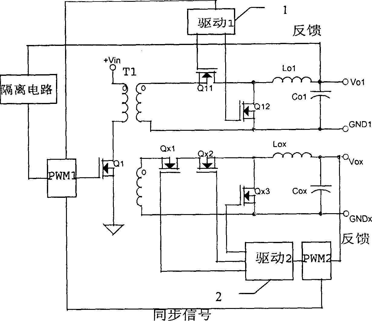
[0023] Such as image 3 A specific implementation circuit of the present invention shown includes a first pulse width modulator PWM1, a second pulse width modulator PWM2, a first drive circuit 1, a second drive circuit 2, an isolation circuit, a transformer T1, and a power switch tube Q1 , the main output circuit and at least one auxiliary output circuit, the primary winding of the transformer and the power switch tube Q1 are connected in series between the input voltage and the ground, the secondary winding of the transformer is connected to the main output circuit and the auxiliary output circuit, in the main output circuit and the auxiliary output circuit A rectification circuit is included, and the rectification circuit in the main output circuit is a synchronous rectification circuit, and the synchronous rectification circuit includes a synchronous rectification field effect transistor Q11 and a synchronous freewheeling field effect transistor Q12. The main output circuit...


PUM


Abstract

The present invention aims at strengthening the load capacity of the subsidiary circuit in multiplex output circuit and adopts rectifier circuit in both main and subsidiary output circuit, with the rectifier circuit in the main output circuit being synchronous one. When the main circuit has light load or is in discontinuous conducting mode, the output filter capacitor may form its discharge loop via output filter inductor and switching FET to avoid wave loss in the primary FET, and ensure the enough great duty ratio of primary main power transistor and the load carrying capacity of the subsidiary output circuit even if in light main output circuit load. In addition, using synchronous rectifying tansistor with greatly lowered loss to replace diode can raise the circuit efficiency greatly to meet the requirement of low voltage great current application.

Description

technical field [0001] The present invention relates to a multi-output circuit, in particular to a multi-output circuit using synchronous rectification. Background technique [0002] At present, DC / DC power modules with multiple outputs are being used more and more widely. The circuit topology used mainly includes: forward converter + Buck converter (Forward + Buck), forward converter + magnetic amplifier (Forward + Magamp), and the use of secondary side post regulators (Secongdary Side PostRegulators). A common topology such as figure 1 . The circuit has the advantages of high efficiency, high switching frequency and small volume. However, this circuit topology also has the following disadvantages: when the main circuit output voltage Vo1 is light-loaded and the circuit is in discontinuous conduction mode, since the main circuit load filter capacitor has no discharge circuit, the pulse of the main power switch tube on the primary side is lost, resulting in secondary The...

Claims


Application Information

Patent Timeline
Patent Type & Authority Patents(China)
IPC IPC(8): H02M3/28
Inventor 田龙中刘浩
Owner ASTEC POWER SUPPLY (SHENZHEN) CO LTD
Why Eureka
Try Eureka