Device and method for manufacturing soft metal tube

A manufacturing method and a technology for a manufacturing device, which are applied in the field of manufacturing and manufacturing devices of metal flexible pipes, can solve the problems of difficult unwinding of copper pipes, and achieve the effect of saving space and reducing costs of the device.

Inactive Publication Date: 2005-08-17
DAIKIN IND LTD
View PDF0 Cites 0 Cited by
  • Summary
  • Abstract
  • Description
  • Claims
  • Application Information

AI Technical Summary

Problems solved by technology

Therefore, there is a disadvantage that the copper tube (B) on the reel becomes difficult to unwind

Method used


Image

  • Device and method for manufacturing soft metal tube
  • Device and method for manufacturing soft metal tube
  • Device and method for manufacturing soft metal tube

Examples


Embodiment Construction

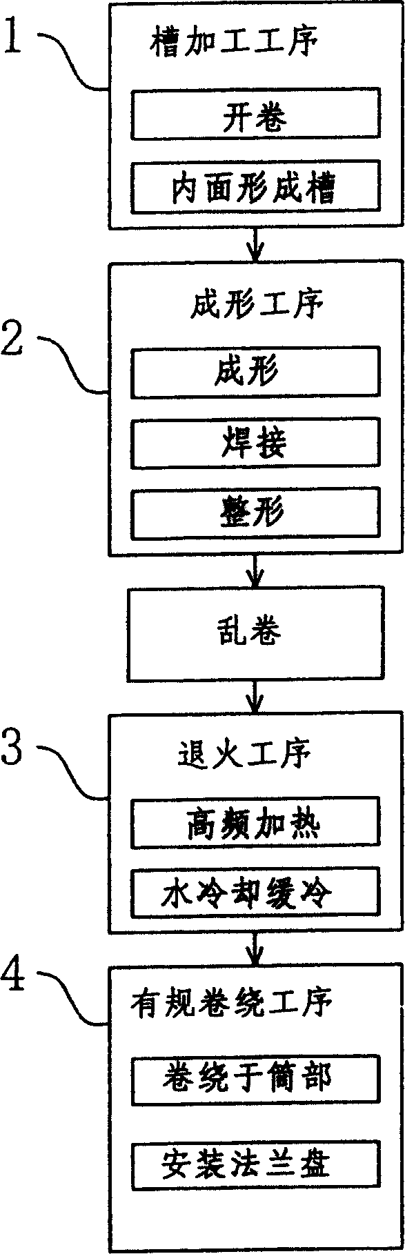
[0048] Hereinafter, embodiments of the present invention will be described with reference to the drawings.

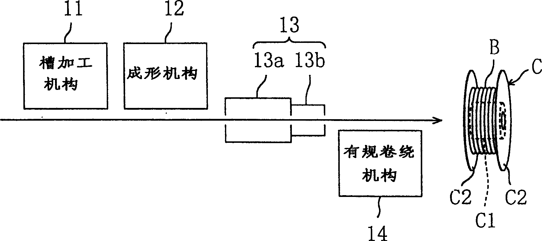
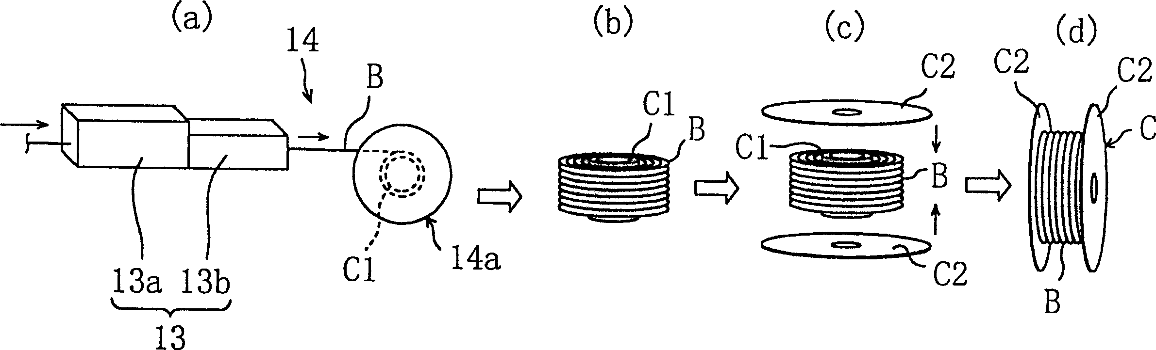
[0049] figure 2 It is a schematic diagram showing the overall configuration of a heat transfer tube manufacturing apparatus according to an embodiment of the present invention.

[0050] This device is a device assembled to a heat exchanger with a strip-shaped long soft copper plate (described in the conventional technical item) with a thickness of about 0.5 mm and a width of about 30 mm. The above-mentioned manufacturing apparatus is used for manufacturing a heat transfer tube (B) having a diameter of several mm (for example, 7 mm to 8 mm) with internal grooves.

[0051] The aforementioned manufacturing device, as a basic structure, includes: a groove machining mechanism (11) that forms a plurality of grooves on the soft copper plate by rolling; the copper plate that is grooved by the groove machining mechanism (11) is formed into a heat transfer The forming mechanis...


PUM

PropertyMeasurementUnit
elongationaaaaaaaaaa

Abstract

Firstly, a heat transfer tube, in which grooves are formed on its inside surface in groove working step (1) and then its forming is applied in forming step (2), is softened in annealing step (3). Then, the tube is coiled in line in coiling in-line step (4). Here, while supplied in the length direction, the heat transfer tube is heated and cooled in the annealing step (3). Further, in the coiling in-line step (4), the heat transfer tube is coiled in line on a body of bobbin, so that works of installing the heat transfer tube to the bobbin can be simplified.

Description

technical field [0001] The invention relates to a manufacturing method and a manufacturing device of a flexible metal tube. The manufacturing method and device of the flexible metal tube are carried out simultaneously during the manufacturing process of a heat transfer tube with grooves on the inner surface used in a heat exchanger. Hardening processing occurs. In particular, the present invention relates to a countermeasure for preventing contact portions of metal pipes from sticking to each other during regular (positioning) winding. Background technique [0002] For example, in the case of fabricating a heat transfer tube with inner grooves for an interlaced fin coil of an air conditioner described in JP-A-61-32599, a soft copper plate is used as the material. For such a soft copper plate, for example, a copper alloy plate material specified in "O material" of the alloy number "C1220" in "Table 4 Mechanical Properties" of JISH3300 "Copper and copper alloy plate and lath"...

Claims


Application Information

Patent Timeline
Patent Type & Authority Patents(China)
IPC IPC(8): F16L9/02B21C37/06B21C37/08B21C37/083B21C37/20B21C47/00B21C47/26B21C47/28C21D9/08C21D9/60C22F1/00C22F1/08F28F1/40F28F21/08
CPCB21C37/083B21C47/26B21C37/202B21C47/00C22F1/08C21D9/60C21D9/08B21C47/28B21C37/06Y02P10/25B21C37/15F28F21/08
Inventor 冈本哲彰城英树中尾德章
Owner DAIKIN IND LTD
Why Eureka
Try Eureka