Garbage incinerator integrating fluidized incineration and moving cold slag into one integral and method

A waste incinerator, cold slag technology, applied in the direction of combustion method, incinerator, combustion type, etc., can solve the problems of endangering the safe operation of the fluidized bed boiler, no energy contribution in the combustion process, and affecting the continuous operation of the incinerator, etc. The slag is convenient, the manufacture is simple, and the effect of simplifying the waste pretreatment system

Inactive Publication Date: 2005-07-06
ZHEJIANG UNIV
View PDF0 Cites 1 Cited by
  • Summary
  • Abstract
  • Description
  • Claims
  • Application Information

AI Technical Summary

Problems solved by technology

However, there is a problem that must be solved in the fluidized bed incineration method. Because the garbage is not sorted, in the primary garbage incinerated, inorganic substances such as construction waste and metals account for 20% or even higher by weight. The combustion process has no energy contribution, and there is still a lack of better pre-furnace sorting equipment to separate them from garbage
Although an electromagnetic iron remover can be installed in the pretreatment system, due to the strong entanglement of the primary waste, some metals still enter the furnace; although it is crushed by a specially developed waste crusher in the waste warehouse, it is still difficult to meet the requirements of fluidization. The particle size requirements of the furnace material for bed operation
These non-combustible components left in the furnace will seriously affect the fluidization quality, affect the continuous operation of the incinerator, and even endanger the normal and safe operation of the fluidized bed boiler

Method used


Image

  • Garbage incinerator integrating fluidized incineration and moving cold slag into one integral and method
  • Garbage incinerator integrating fluidized incineration and moving cold slag into one integral and method

Examples


Embodiment Construction

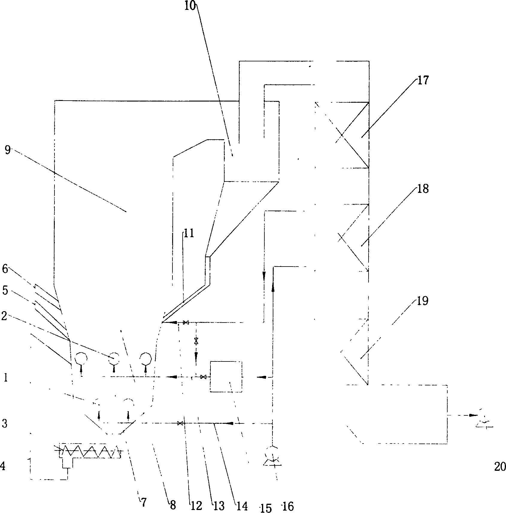
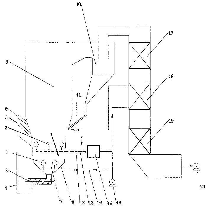
[0010] The waste incinerator integrating fluidized incineration and moving cold slag has a furnace. The furnace is divided into a mobile cooling zone 7, a fluidized zone 8, and a dilute phase zone 9. Pipe 1, slag discharge screening machine 3, fine sand lifting and feeding device 4, a separator 10 is provided at the outlet of the furnace, the separator is connected to a return device 11, the lower end of the return device is connected to the furnace fluidized zone, and the separator outlet is connected to the furnace in turn Superheater 17, air preheater 18, economizer 19, induced draft fan 20, coal feeder 5, waste feeder 6, blower 16, cold primary air duct 14, lower air distribution duct 1 The air blower 16 is connected with the igniter 15, the primary air duct 13, and the upper air distribution pipe 2, the lower end of the air preheater 18 is connected with the blower 16, the outlet of the air preheater 18 is connected with the secondary air duct 12, and the return device 11 ...


PUM


Abstract

The invention discloses a garbage incinerator and method integrating fluidized incineration and moving cold slag. It adopts an upper fluidization zone and a lower moving zone to form an integrated bed of fluidization and movement in the incinerator; The fluidized area and the moving area on the lower floor are ventilated by the air distribution pipe with openings. After the garbage is put into the incinerator by the feeding device, the combustible components of the garbage are fluidized and burned in the upper fluidized area and the furnace. , the temperature of the upper fluidized zone is maintained at 800-950°C, and the non-combustible components are slowly passed through the lower moving zone in the form of a moving bed and then discharged in the form of large slag. The temperature of the large slag can be reduced to 150°C or even lower. The present invention does not have the traditional air distribution plate air distribution device, simple manufacture, low investment, suitable for large-scale development; convenient slag discharge, can simplify the waste pretreatment system of the fluidized bed; waste burning, large slag cooling in the fluidization movement It is carried out in an integrated bed, and low-temperature large slag can be discharged after combustion, without adding a slag cooler outside the furnace.

Description

technical field [0001] The invention relates to a garbage incinerator and a method integrating fluidized incineration and moving cold slag. Background technique [0002] According to statistics, in 2000, the annual output of municipal solid waste in the whole country has reached 150 million tons, and it is increasing at a rate of more than 7% per year. The large amount of municipal solid waste has seriously affected the urban landscape and quality of life. The incineration method can better achieve the goals of waste reduction, harmlessness and resource utilization, and has already begun to be applied and promoted in some large and medium-sized cities in my country. One of the combustion methods put into commercial operation at present is grate incinerator, including multi-level stepped chain grate, inclined reciprocating grate and sending type Martin grate, etc. Its advantage is that it does not require pretreatment of garbage, but The shortcomi...

Claims


Application Information

Patent Timeline
Patent Type & Authority Patents(China)
IPC IPC(8): F23G5/02F23G5/30
Inventor 严建华池涌马增益李晓东蒋旭光金余其杨家林王飞倪明江岑可法
Owner ZHEJIANG UNIV
Why Eureka
Try Eureka