
Poor residual hydroconversion method

A technology for residual oil and oil and gas, which is applied in the field of hydrocracking of heavy and residual oil. It can solve the problems of increasing the amount of coking in the reactor, reducing the value of distillate oil, and high condensation reaction speed, so as to improve the conversion rate of residual oil and reduce dryness. Gas yield, reduce the effect of coking reaction

Inactive Publication Date: 2005-06-08
CHINA PETROLEUM & CHEM CORP +1
View PDF4 Cites 5 Cited by
  • Summary
  • Abstract
  • Description
  • Claims
  • Application Information

AI Technical Summary

Problems solved by technology

The cracking direction in the cracking reaction of residual oil is mainly the alkyl side chain and cycloalkane ring cracking of alkanes and aromatics to generate alkanes and small molecule aromatics. When the alkanes and small molecule aromatics in the residue stream no longer maintain The stable colloidal state of the asphaltene will break the adsorption balance and move the balance towards the micelles, resulting in the loss of the peptized state of asphaltene and the formation of flocculated coagulants. , the result will increase the amount of coking in the reactor and affect the operating life of the device
In addition, if the alkanes and small molecular aromatics produced in the cracking reaction of residual oil are not removed from the reactor in time, they will further undergo cracking reactions to generate smaller molecules or even dry gas, which will reduce the value of distillate oil. and increased hydrogen consumption

Method used


Image

  • Poor residual hydroconversion method
  • Poor residual hydroconversion method

Examples


Embodiment 1~6

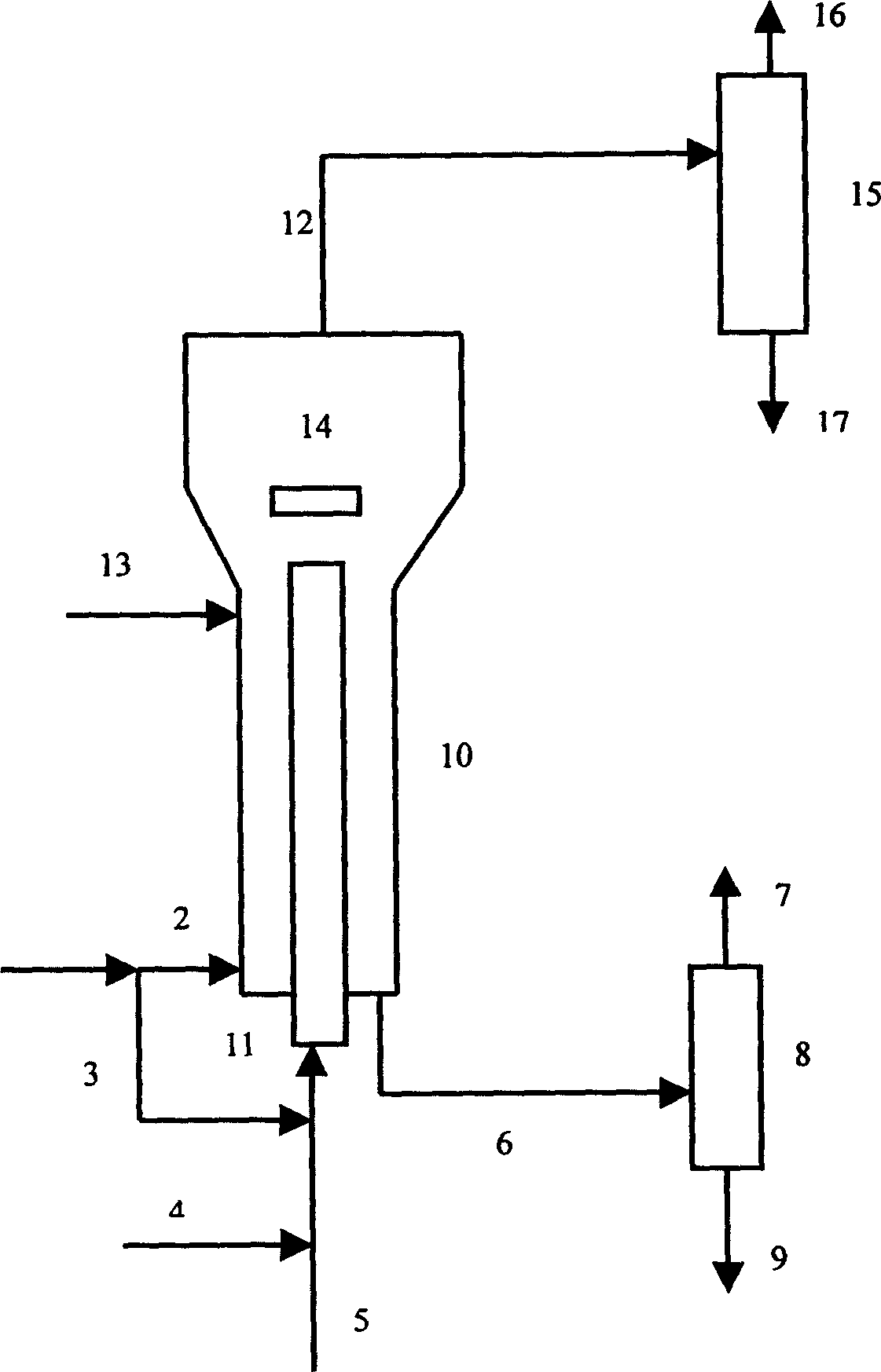
[0021] This test mainly investigates the coking performance of the tube-in-tube separation slurry bed hydrogenation process and the existing slurry bed process. The catalyst prepared in Example 9 of the published patent CN1045307C was used as the catalyst in this test. The catalyst was a water-soluble catalyst with a Mo content of 5.6w%, Ni of 0.7w%, and a p / Mo atomic ratio of 0.087. In this experiment, the residual oil slurry bed hydrogenation reaction was carried out on a continuous test device. Based on the total weight of the feed oil and the catalyst entering the reactor, the content of the catalyst in the reactor is 300 ppm. The properties of raw materials and aromatic feed are shown in Table-1, and the operating conditions and reaction results are shown in Table-2. Table-2 shows that the coking performance of the tube-in-tube separation slurry bed hydrogenation process is much lower than the existing slurry bed process, and the tendency of excessive cracking is also lower t...

Embodiment 7~10

[0027] This test mainly investigates the coke deposition of the slurry bed process of the present invention and the existing slurry bed process. The catalyst was the same as in Examples 1 to 6, and the device operated for 360 hours. The test results are shown in Table-3, and it can be seen from Table-3 that the amount of coke deposition in the slurry bed process of the present invention is much smaller than that of the existing slurry bed process.

[0028] Example

[0029] Example


PUM

PropertyMeasurementUnit
volume ratioaaaaaaaaaa

Abstract

The invention provides a residual oil hydrocracking method, which adopts a tube-in-tube reactor, and a gas-liquid separator is arranged on the top of the inner tube. The separator is separated, the gas phase is discharged from the reactor, and the liquid phase enters the loop reaction section together with the added hydrocarbon oil containing more heavy aromatics, and at the same time hydrogen is added at the bottom of the loop reaction section. Compared with the prior art, the method of the invention has the advantages of uniform reactor temperature, less coke deposition, reduced dry gas output and the like. The method of the invention is mainly applicable to the hydrocracking reaction of heavy and residual oil, especially the hydrocracking reaction of inferior heavy and residual oil.

Description

1. Technical field [0001] The invention relates to a method for hydrocracking heavy and residual oil, in particular to a method for hydrocracking the residual oil in a slurry bed reactor. 2. Background technology [0002] Residue slurry bed reactor hydrocracking process technology can deeply convert inferior heavy residual oil to produce lighter secondary processing raw materials, and the product distribution of the device is flexible. At present, the slurry-bed hydrogenation process adopts fine powder or liquid homogeneous catalyst (or additive) mixed with feed oil and then enters the reactor in the upstream form together with hydrogen to complete the hydrothermal cracking reaction. The difference is that it uses The coking inhibitors and / or catalysts are different. [0003] Research has been conducted on additives that can inhibit the coking reaction or remove coke from the reactor. Canadian Patent 1,073,389 issued by Ternan et al. on March 10, 1980 and U.S. Patent 4,214,977 is...

Claims


Application Information

Patent Timeline
Patent Type & Authority Patents(China)
IPC IPC(8): C10G47/22
Inventor 晋梅韩保平
Owner CHINA PETROLEUM & CHEM CORP
Learn More