Implanting machine in paddy field

A technology for working machines and paddy fields, applied in agricultural machinery and implements, chassis of agricultural implements, agriculture, etc., can solve problems such as rising costs and complicated structures, and achieve cost reduction, sufficient lubricating oil, and restraint oil temperature. rising effect

Inactive Publication Date: 2005-03-09
KUBOTA LTD
View PDF1 Cites 0 Cited by
  • Summary
  • Abstract
  • Description
  • Claims
  • Application Information

AI Technical Summary

Problems solved by technology

[0003] However, in the above-mentioned prior art, since the clutch is provided at the front portion of the hydrostatic continuously variable transmission, when the clutch is a wet multi-plate clutch with good durability, a clutch case with a built-in clutch other than the gearbox is required. Complicated the structure and increased the cost

Method used


Image

  • Implanting machine in paddy field
  • Implanting machine in paddy field
  • Implanting machine in paddy field

Examples


Embodiment Construction

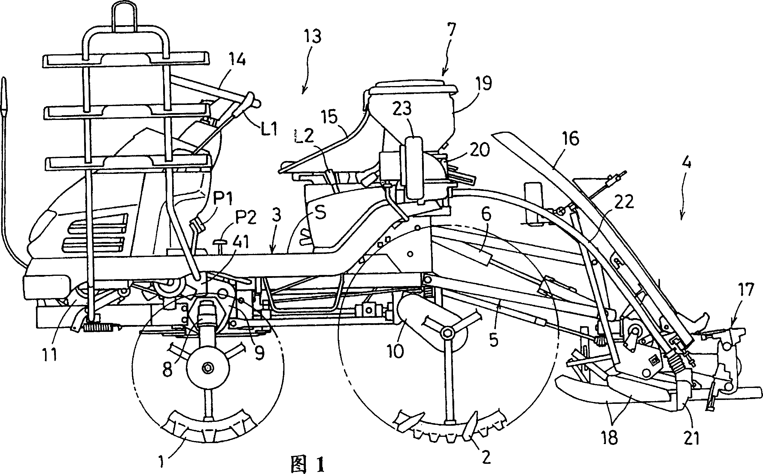
[0035] Hereinafter, the description of the present invention will be made with reference to the accompanying drawings showing a rice transplanter as an example of a paddy field operation machine.

[0036] Examples will be described.

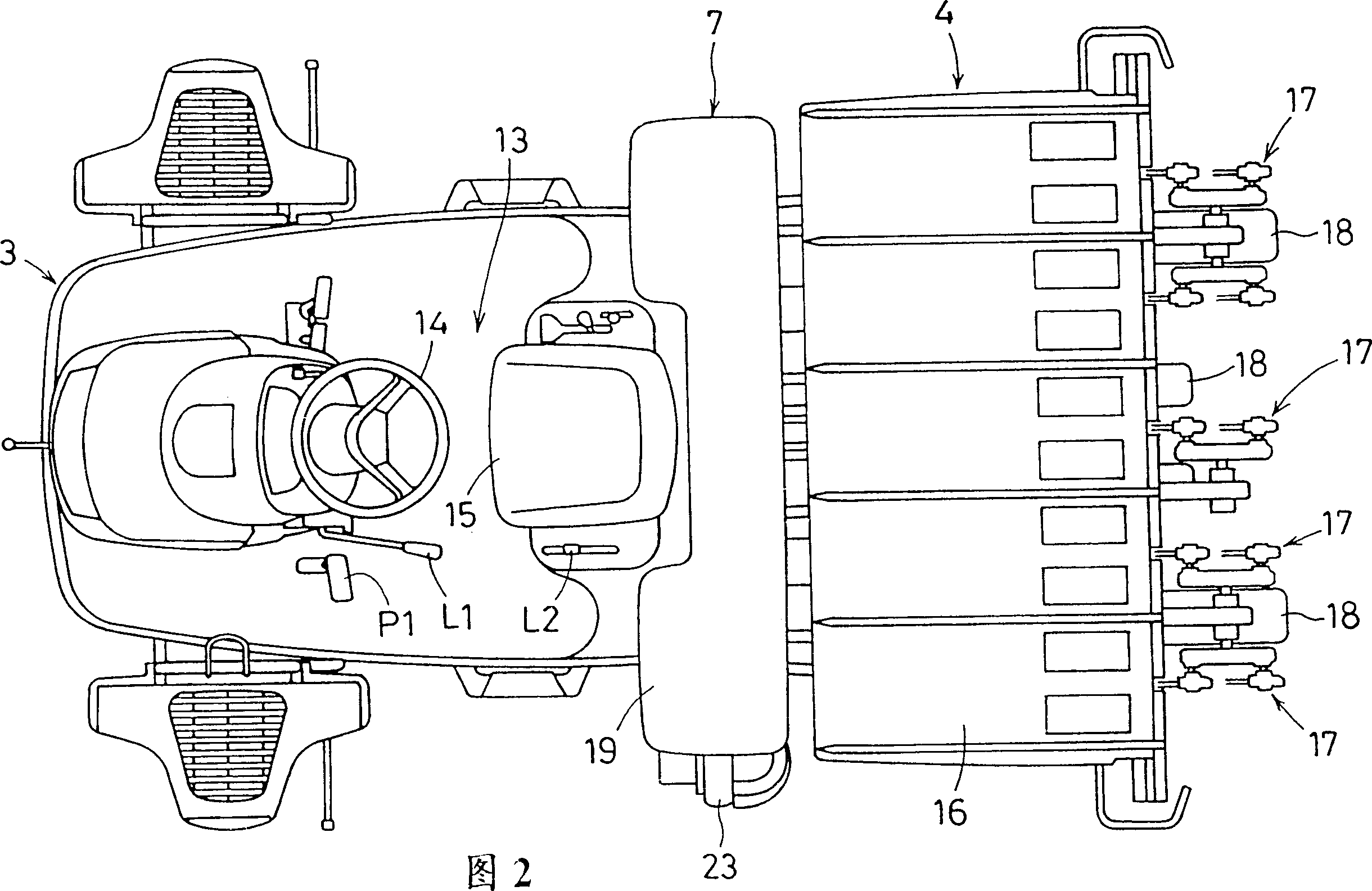
[0037] As shown in Figure 1 and Figure 2, this rice transplanter has a left and right pair of driving front wheels (equivalent to front wheels) 1 and a left and right pair of driving rear wheels (equivalent to rear wheels) 2. The rear part of the planting device 4 is connected with a multi-row planting type planting device 4 as an example of a paddy field operation device through a four-bar linkage 5. It is also provided with a lifting hydraulic cylinder 6 and a fertilizing device that utilizes an oil cylinder to lift the planting device 4. 7.

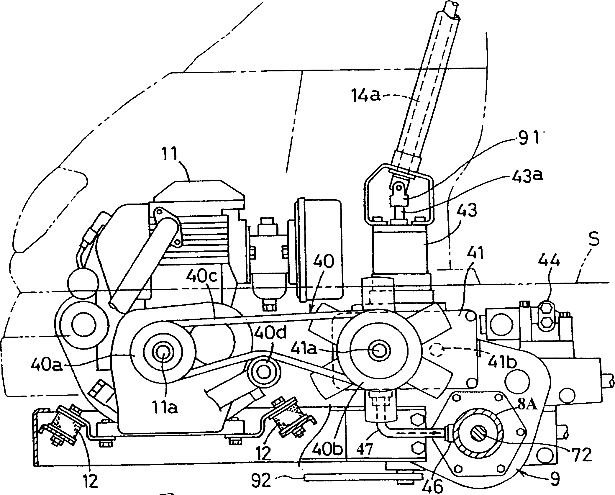
[0038] self-propelled body 3 as image 3 , Figure 4 As shown, there is a gearbox 9 that drives the front wheels 1 through the front axle box 8. At the same time, in the body frame that drives the rear ...


PUM


Abstract

To compact the size of a torque generator. A torque generator 43 for the hydraulic power steering is linked to the upper face of the transmission case 9 arranged above the front steering wheel 1, the vertical rotary shaft that is synchronously connected to this torque generator 43 is synchronously linked to the pitman arm shaft 92a. In addition, an intermediate joint 99 that is equipped with the interlocking part that is relatively swingable and torque-transmittably fitted to the swing motion- outputting shaft 43b of the torque generator 43 and with the output unit to the vertical rotary shaft 95 is supported by the transmission case 9 rotatably around the vertical shaft axis P.

Description

technical field [0001] The invention relates to a paddy field operation machine such as a rice transplanter equipped with a clutch, a hydrostatic stepless transmission device and a gearbox, and in particular relates to a technology with a simple car body structure and good operability. Background technique [0002] In the past, the transmission device of the paddy field working machine is disclosed in the Japanese Patent Application Publication No. 10-54461, which is equipped with a clutch for connecting and disconnecting the engine power and a hydrostatic continuously variable transmission device that receives the output of the clutch. The output of the continuously variable transmission is transmitted to the transmission body. [0003] However, in the above-mentioned prior art, since the clutch is provided at the front portion of the hydrostatic continuously variable transmission, when the clutch is a wet multi-plate clutch with good durability, a clutch case with a built-...

Claims


Application Information

Patent Timeline
Patent Type & Authority Patents(China)
IPC IPC(8): A01B51/02A01B69/00A01C11/02B60K17/10F16D13/52F16H61/40
CPCA01B51/02A01B69/00A01C11/02B60K17/10B60Y2200/22F16D13/52F16H61/40
Inventor 洼津诚山下真小谷伸介松木直树清水孝式
Owner KUBOTA LTD
Why Eureka
Try Eureka