Hydraulic pressure supply device for industrial vehicle

A technology for hydraulic supply and industrial use, applied in transmission, fluid transmission, transmission control, etc., can solve the problem of not effectively suppressing the rise of oil temperature, oil temperature rise, etc., and achieve the effect of suppressing the rise of oil temperature

Inactive Publication Date: 2013-03-27
K C M
View PDF5 Cites 0 Cited by
  • Summary
  • Abstract
  • Description
  • Claims
  • Application Information

AI Technical Summary

Problems solved by technology

However, in the device described in the aforementioned Patent Document 1, simply increasing the pump discharge rate increases the oil temperature due to an increase in the amount of oil passing through the safety valve, so the increase in oil temperature cannot be effectively suppressed.

Method used


Image

  • Hydraulic pressure supply device for industrial vehicle
  • Hydraulic pressure supply device for industrial vehicle
  • Hydraulic pressure supply device for industrial vehicle

Examples


Embodiment Construction

[0019] Hereinafter, a hydraulic pressure supply device for an industrial vehicle according to an embodiment of the present invention will be described with reference to the drawings.

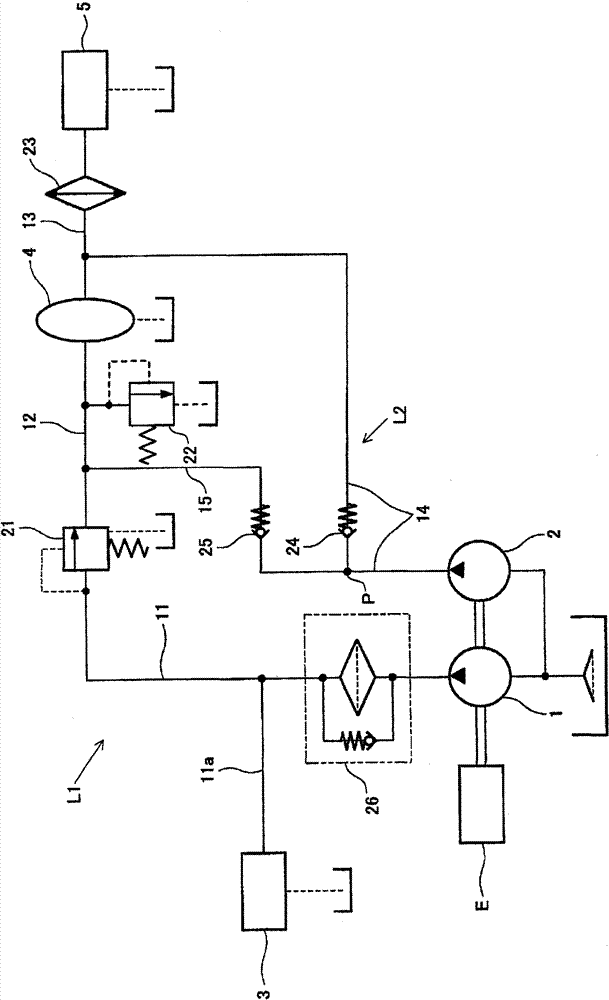
[0020] Figure 4 It is a side view of a wheel loader which is an example of an industrial vehicle to which the hydraulic pressure supply device in this embodiment is applied. The wheel loader 100 is composed of a front body 110 having an arm 111 , a bucket 112 , tires 113 and the like, and a rear body 120 having a cab 121 , an engine compartment 122 , tires 123 and the like. The arm 111 is rotated vertically (pitching) by the drive of the arm hydraulic cylinder 114 , and the bucket 112 is rotated vertically by the drive of the bucket hydraulic cylinder 115 (unloading or loading). The front body 110 and the rear body 120 are rotatably connected to each other by a center pin 101 , and the front body 110 bends left and right relative to the rear body 120 by extending and contracting a steering cyl...


PUM


Abstract

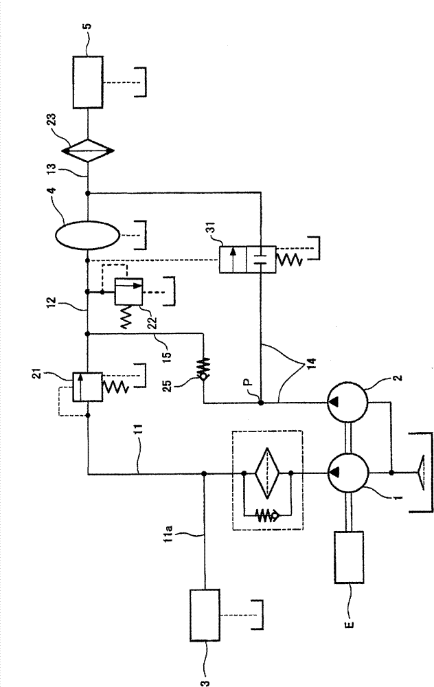
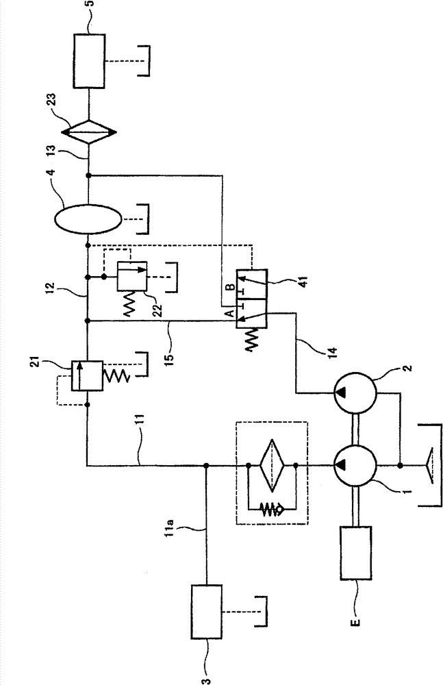
A hydraulic pressure supply device for an industrial vehicle has a first hydraulic pump (1) and a second hydraulic pump (2) that are driven by an engine (E); a first hydraulic circuit (L1) for leading, as clutch control pressure, pressurized oil, which is supplied by the first hydraulic pump (1), to a transmission control device (3) after regulating the pressurized oil by a pressure regulation valve (21), leading as torque converter operation oil the pressurized oil, which has passed through the pressure regulation valve (21), to a torque converter (4), and further leading the pressurized oil, which has passed through the torque converter (4), to an oil cooler (23) ; a safety valve (22) connected to that part of the first hydraulic circuit (L1) which is between the pressure regulation valve (21) and the torque converter (4) and, if the pressure on the entrance side of the torque converter (4) is not lower than a predetermined value (P22), releasing that pressurized oil on the torque converter entrance side to a tank; a second hydraulic circuit (L2) for dividing pressurized oil from the second hydraulic pump (2) to a circuit portion that is downstream of the pressure regulation valve (21) and upstream of the safety valve (22) and to a circuit portion that is downstream of the torque converter (4) and upstream of the oil cooler (23); and a flow control section (24) for changing the proportion of the rate of flow in the second hydraulic circuit (L2) so that the proportion to a circuit part that is downstream of the torque converter (4) and upstream of the oil cooler (23) increases as the pressure at the entrance of the torque converter (4) increases.

Description

technical field [0001] The present invention relates to a hydraulic supply device for industrial vehicles. Background technique [0002] Conventionally, in industrial vehicles such as wheel loaders equipped with a hydraulic torque converter (hereinafter referred to as a torque converter), a device is known in which pressure oil from a hydraulic pump is used as working oil to guide hydraulic pressure. The torque converter is guided to a clutch control control valve of the transmission as a clutch control pressure (for example, refer to Patent Document 1). In the device described in Patent Document 1, a pressure regulating valve is provided in order to make the clutch control pressure supplied to the control valve a predetermined set pressure. The torque converter, and then guide the pressure oil that has passed through the torque converter to the oil cooler. Between the pressure regulating valve and the torque converter, a safety valve is interposed to limit the inlet press...

Claims


Application Information

Patent Timeline
Patent Type & Authority Patents(China)
IPC IPC(8): F16H41/30F16H61/00
CPCF16H61/0031F16H41/30Y10T74/19149Y10T74/19153
Inventor 东宏行岛津淳志吉川正规铃木光世
Owner K C M
Why Eureka
Try Eureka