Tractor transmission device

A technology for transmissions and tractors, applied to transmissions, transmission parts, gear transmissions, etc., can solve problems such as poor oil flow, obstruction of bearings and transmission gears, rise in oil temperature, etc., to achieve optimal configuration and suppress oil The effect of temperature rise and fluidity improvement

Active Publication Date: 2014-08-27
KUBOTA CORP
View PDF7 Cites 0 Cited by
  • Summary
  • Abstract
  • Description
  • Claims
  • Application Information

AI Technical Summary

Problems solved by technology

[0006] In the two prior art mentioned above, the gearbox body is made into an oil pool that communicates front and rear and oil can flow, and an oil passage that communicates the second chamber and the third chamber is formed on the second support wall, but not only in the second The supporting wall supports the main transmission mechanism, the auxiliary transmission mechanism and the output shaft from the upper part to the lower part, and also supports the front wheel power output shaft at the lower part. The flow of oil from the first chamber to the third chamber becomes worse, and the oil temperature rises
In particular, when the transmission mechanism adopts a hydraulic switch type device, since the amount of oil flowing out from the transmission mechanism is large, there is a problem with the fluidity of the oil.

Method used


Image

  • Tractor transmission device
  • Tractor transmission device
  • Tractor transmission device

Examples


Embodiment Construction

[0040] Hereinafter, embodiments of the present invention will be described with reference to the drawings.

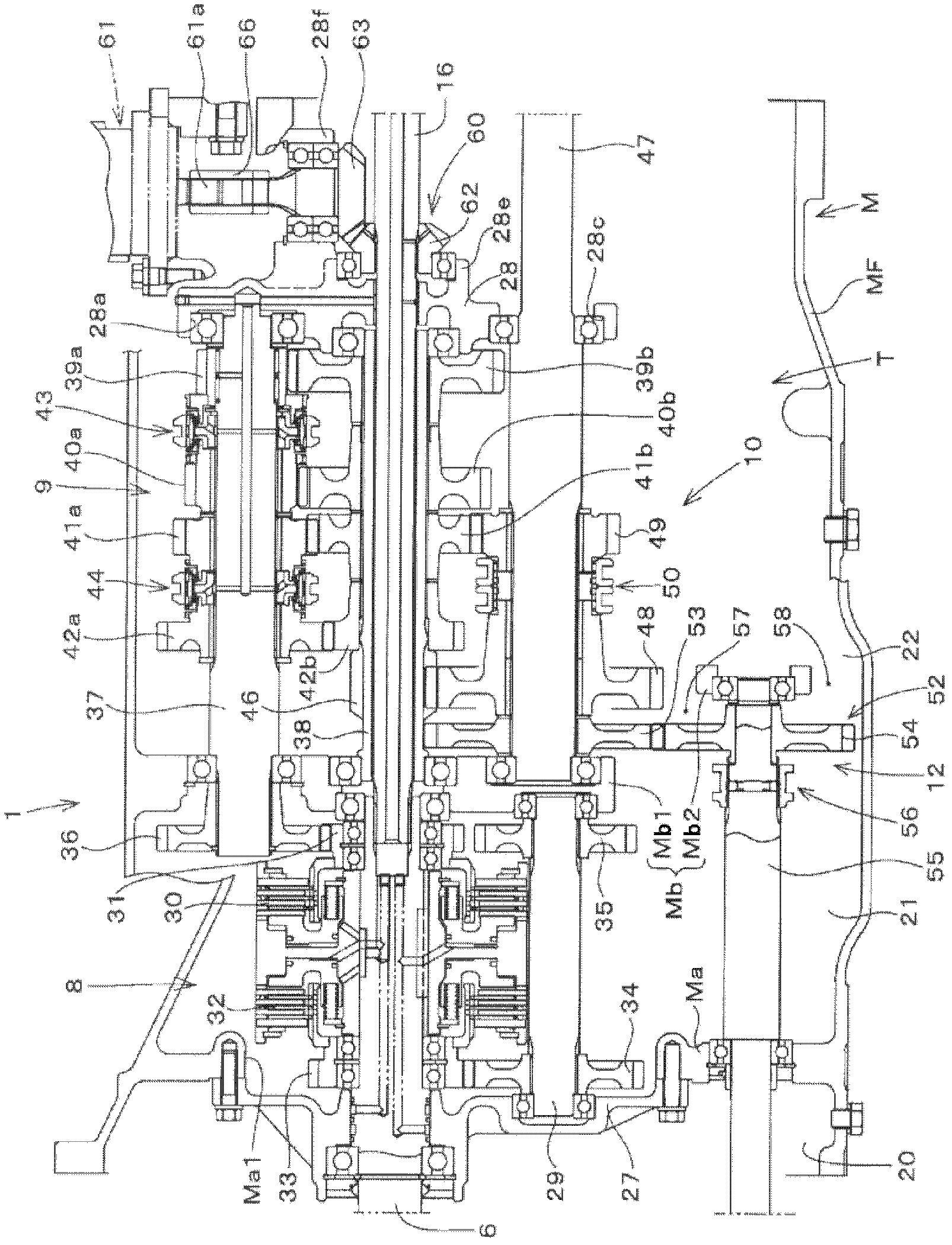
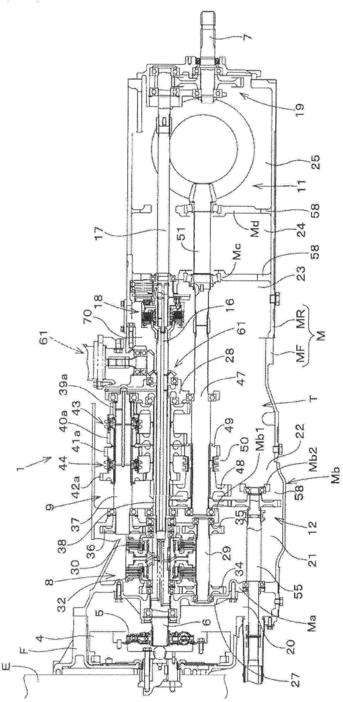
[0041] exist figure 1 , 2 Among them, 1 is the transmission device of the front and rear four-wheel drive tractor, and the rear end side of the flywheel housing F connected to the rear end side of the engine E is connected with a transmission case M, and the transmission case M includes the front and rear transmission case MF , MR, and a transmission device T is accommodated inside them. The vehicle body of the tractor is constituted by the engine E, the flywheel housing F, the transmission case M, and the like.

[0042] The transmission T transmits the power from the engine E to the propulsion shaft 6 through the flywheel 4 and the buffer mechanism 5. 6 PTO drive system that transmits to PTO shaft 7.

[0043] The driving drive system of the transmission device T has: a hydraulic switching type forward and backward switching mechanism (transmission device) 8, which co...


PUM


Abstract

PROBLEM TO BE SOLVED: To improve the fluidity of oil in front and rear of a support wall by vertically separating the support wall for supporting a shift mechanism and a front wheel power takeout shaft and forming an opening opened in the vertical direction and the longitudinal direction therebetween.SOLUTION: A second chamber 21 is provided with an advance / retreat switching mechanism 8 for shifting the power of a propelling shaft 6 to advance / retreat gears, a third chamber 22 is provided with a main shift mechanism 9, a sub-shift mechanism 10 and an output shaft 47, and the front wheel power takeout shaft 55 for transmitting the power of the output shaft 47 by taking out front wheel power via a front wheel power takeout means 52 is supported by the first and second support walls Ma and Mb. The second support wall Mb is separately formed into an upper wall Mb1 for supporting the first shift mechanism 8 and the second shift mechanisms 9, 10 and a lower wall Mb2 for supporting the front wheel takeout shaft 55, and the opening 57 opened in the vertical direction and the longitudinal direction is formed between the upper wall Mb1 and the lower wall Mb2.

Description

technical field [0001] The invention relates to a transmission device of a tractor with a front wheel power output shaft. Background technique [0002] With regard to the prior art of tractor transmissions, as disclosed in Patent Document 1, first and second support walls are provided inside the gearbox body connected to the flywheel housing, and the first and second support walls communicating with the inside of the flywheel housing are respectively formed. The first room, the second room in the middle, and the third room in the rear, the second room and the third room are oil pools, and the second room is equipped with a plurality of transmission mechanisms for the driving system that changes the power of the propulsion shaft , on the second supporting wall separating the rear part of the second chamber, a front wheel power output shaft for outputting the power output by the transmission mechanism through the front wheel power output unit as front wheel drive is supported....

Claims


Application Information

Patent Timeline
Patent Type & Authority Patents(China)
IPC IPC(8): F16H3/091F16H57/021
CPCF16H37/043F16H57/021F16H57/023F16H2057/0235
Inventor 辻贤一朗
Owner KUBOTA CORP
Why Eureka
Try Eureka