Fuel cell system and method for controlling fuel cell system
a fuel cell and system technology, applied in battery/fuel cell control arrangement, electrochemical generators, transportation and packaging, etc., can solve the problems of limiting the output of the compressor, occurrence of failure, and patent literature 2 does not disclose the measures to be taken when air pressure has decreased, so as to reduce the rotational speed of the compressor, stabilize the fuel cell operation, and suppress the rise of the oil temperature of the compressor.
- Summary
- Abstract
- Description
- Claims
- Application Information
AI Technical Summary
Benefits of technology
Problems solved by technology
Method used
Image

Examples
first embodiment
Explanation of First Embodiment
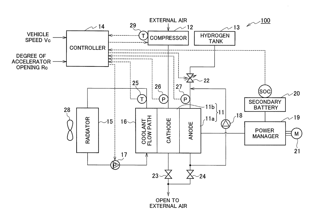
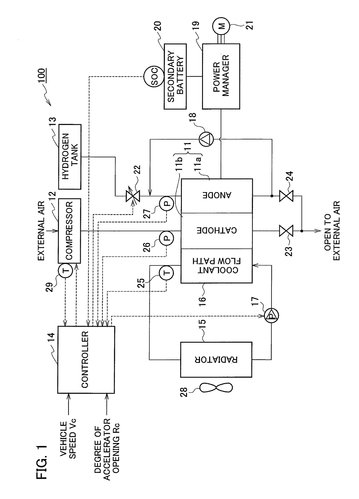
[0022]FIG. 1 is a block diagram illustrating a configuration of a fuel cell system according to a first embodiment. As illustrated in FIG. 1, a fuel cell system 100 according to the first embodiment mainly includes a fuel cell 11, a coolant flow path 16, a controller 14, a compressor 12, a hydrogen tank 13, a radiator 15, a coolant pump 17, and a hydrogen circulation pump 18.
[0023]The fuel cell 11, having an anode 11a and a cathode 11b, generates electric power by chemical reaction between air (oxidation gas) being supplied to the anode 11a and hydrogen (fuel gas) being supplied to the cathode 11b. In addition, the fuel cell 11 is connected to a power manager 19.
[0024]The power manager 19 supplies electric power output from the fuel cell 11 to a motor 21. In addition, the power manager 19 performs a control of charging of a secondary battery 20 or supplying electric power output from the secondary battery 20 to the motor 21.
[0025]The secondary battery ...
second embodiment
Explanation of Second Embodiment
[0049]Next, a second embodiment of the present invention will be described. The system configuration is similar to that of FIG. 1 described above and therefore explanation thereof will be omitted. Hereinafter, a processing procedure of the fuel cell system 100 according to the second embodiment will be described with reference to the flowchart illustrated in FIG. 4 and the timing chart illustrated in FIG. 5.
[0050]Similarly to the first embodiment, initially, the fuel cell 11 is supposed to be stably operating. In other words, the pressure of the anode 11a and the pressure of the cathode 11b are supposed to be the pressure during normal operation, and the temperature of the coolant is supposed to be the temperature during the normal operation.
[0051]At step S21 of FIG. 4, the controller 14 obtains the oil temperature Tc of the compressor 12 detected by the oil temperature sensor 29. The controller 14 then compares the oil temperature Tc with the oil tem...
third embodiment
Explanation of Third Embodiment
[0063]Next, a third embodiment of the present invention will be described. The system configuration is similar to that of FIG. 1 described above and therefore explanation thereof will be omitted. Hereinafter, a processing procedure of the fuel cell system 100 according to the third embodiment will be described with reference to the flowchart illustrated in FIG. 6 and the timing chart illustrated in FIG. 7.
[0064]Similarly to the first and the second embodiments, initially, the fuel cell 11 is supposed to be stably operating. In other words, the pressure of the anode 11a and the pressure of the cathode 11b are supposed to be the pressure during normal operation, and the temperature of the coolant is supposed to be the temperature during the normal operation.
[0065]At step S31 of FIG. 6, the controller 14 obtains the oil temperature Tc of the compressor 12 detected by the oil temperature sensor 29. The controller 14 then compares the oil temperature Tc wit...
PUM
| Property | Measurement | Unit |
|---|---|---|
| electric power | aaaaa | aaaaa |
| temperature | aaaaa | aaaaa |
| pressure | aaaaa | aaaaa |
Abstract
Description
Claims
Application Information
 - R&D
- Intellectual Property
- Life Sciences
- Materials
- Tech Scout
- Unparalleled Data Quality
- Higher Quality Content
- 60% Fewer Hallucinations
Browse by: Latest US Patents, China's latest patents, Technical Efficacy Thesaurus, Application Domain, Technology Topic, Popular Technical Reports.
© 2025 PatSnap. All rights reserved.Legal|Privacy policy|Modern Slavery Act Transparency Statement|Sitemap|About US| Contact US: help@patsnap.com