Vacuum extruder of brick or tile

A vacuum extruder and extruder technology, which is applied in the field of brick and tile machinery and equipment, can solve the problems of large volume, inability to mix mud evenly, and unsatisfactory extrusion effect.

Inactive Publication Date: 2004-12-22
程玉全
View PDF1 Cites 1 Cited by
  • Summary
  • Abstract
  • Description
  • Claims
  • Application Information

AI Technical Summary

Problems solved by technology

Its disadvantages are that the upper and lower levels are overlapped and connected, the structure is complex, the volume is large, the energy consumption is large, and the cost is high.
[0003] Chinese patent No. ZL91110680 discloses a single-column single-rotation single-stage extruder. The auger shaft adopts a single-structure helical auger, which cannot evenly stir the mud. The material control mechanism consumes power and the extrusion effect is not very ideal

Method used


Image

  • Vacuum extruder of brick or tile
  • Vacuum extruder of brick or tile

Examples


Embodiment Construction

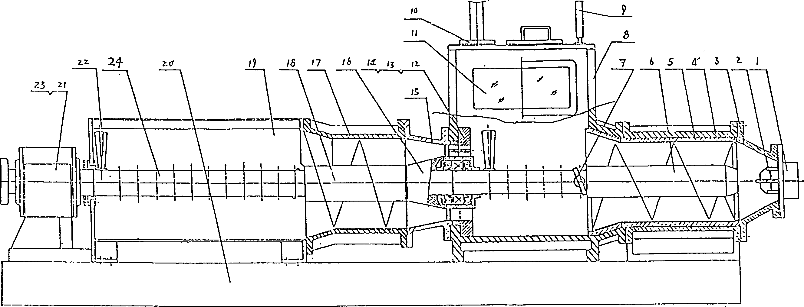
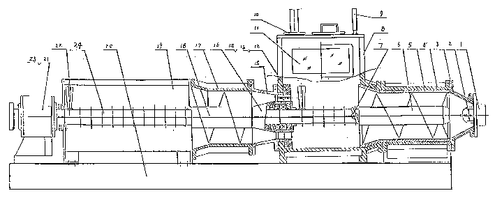
[0015] Referring to the accompanying drawings, the machine mouth 1, mandrel frame 2, and machine head 3 are fixed on the outlet of the mud cylinder 4 behind the vacuum chamber. There is a bushing 5 inside the mud cylinder 4, and the top of the vacuum chamber passes through the flange and the exhaust pipeline. 10 links to each other, and rear mud cylinder 4 is horizontally connected with taper mud cylinder 15, half mud cylinder 17, mixing box 19 through vacuum chamber 8. The reamer shaft 24 is sequentially equipped with a rear thrust bearing group 23, a stirring tooth 22, a Huff stirring knife 18, a taper sleeve 16, a bearing 13, a sealing assembly 14, a stirring knife 7, and an extrusion stirring knife 6 from back to front. Simultaneously, the middle part of the reamer shaft 24 is fixedly connected with the support bearing seat 12, the bearing 13, the sealing assembly 14 and the vacuum chamber 8.

[0016] When working, the same as the operation of the upper and lower double-st...


PUM


Abstract

A vacuum extruder for making bricks and tiles is composed of stirring unit, extruding-out unit and a vacuum chamber between them. The stirring shaft passes through said stirring unit, vacuum chamber and extruding-out unit. The stirring teeth in stirring box and vacuum chamber can perform the stirring, feeding and quatitative transmission functions. Its advantages are simple structure and high extruding out effect.

Description

technical field [0001] The invention belongs to the field of brick and tile mechanical equipment, in particular to a vacuum brick and tile extruder. Background technique [0002] Existing two-stage vacuum extruders, regardless of high-low layer type or compact type, are composed of upper-stage agitation and lower-stage extrusion. Cylinder, taper mud cylinder, taper sleeve, vacuum chamber. The lower extrusion is composed of lower support seat, reamer, machine head, machine mouth and core tool. Its disadvantages are that the upper and lower levels are overlapped and connected, the structure is complex, the volume is large, the energy consumption is large, and the cost is high. [0003] Chinese patent No. ZL91110680 discloses a single-column single-rotation single-stage extruder. The auger shaft adopts a single-structure helical auger, which cannot evenly stir the mud. The material control mechanism consumes power and the extrusion effect is not very ideal. Contents of the...

Claims


Application Information

Patent Timeline
Patent Type & Authority Patents(China)
IPC IPC(8): B28B3/22
Inventor 程玉全郭宽义达拉成郭宽怀程海涛郭宽宏
Owner 程玉全
Why Eureka
Try Eureka