Method and circuit for detecting data division synchronus signals in high-clearity television

A technology for high-definition television and synchronization signals, which can be used in high-definition television systems, synchronization signal speed/phase control, and components of color televisions, etc., and can solve problems such as multiple doors.

Inactive Publication Date: 2004-09-29
SAMSUNG ELECTRONICS CO LTD
View PDF1 Cites 0 Cited by
  • Summary
  • Abstract
  • Description
  • Claims
  • Application Information

AI Technical Summary

Problems solved by technology

Therefore conventional devices require too many doors to perform their functions

Method used

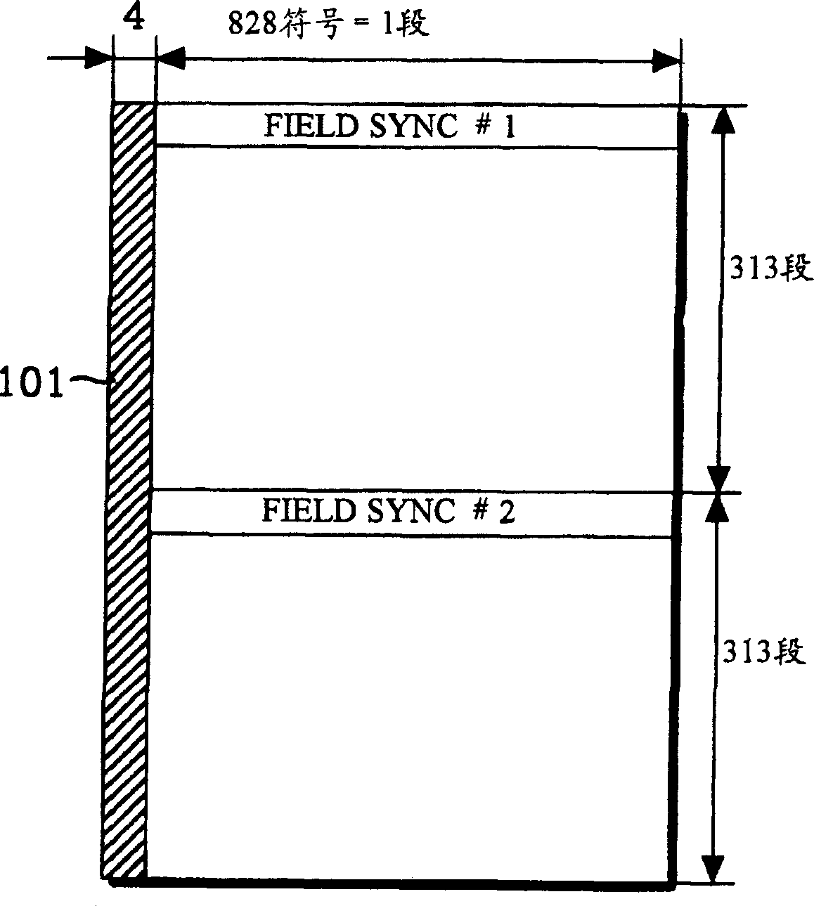
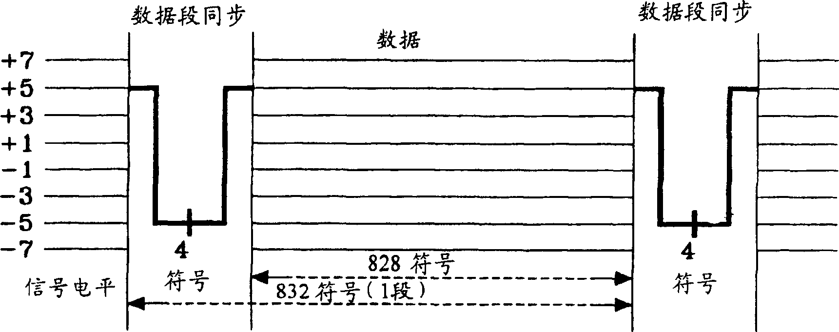
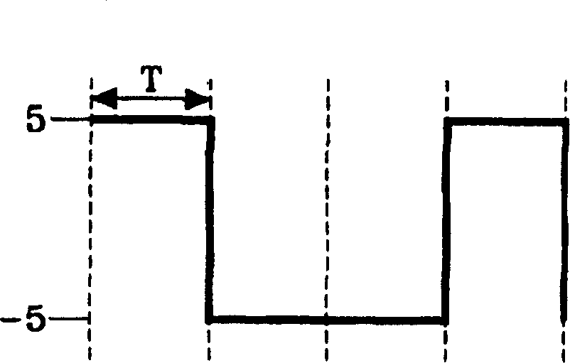

Image

  • Method and circuit for detecting data division synchronus signals in high-clearity television
  • Method and circuit for detecting data division synchronus signals in high-clearity television
  • Method and circuit for detecting data division synchronus signals in high-clearity television

Examples


Embodiment Construction

[0020] FIG. 4 is a block diagram of a segment sync signal detection circuit of a GA-VSB HDTV system according to an embodiment of the present invention. As shown in Figure 4, the data segment synchronous signal detection circuit of the present invention is in such a way / constituted that a hardware limiter 400 is added between the four-symbol correlator 305 and the adder 307 to obtain a three-level value for the 4bit input 2 bit output.

[0021] Figure 5 The circuitry of the hardware limiter 400 of FIG. 4 is shown in detail. The hardware limiter is composed of the following: a separator 501 for separating the MSB from the four bits output by the four-symbol correlator 305; A comparator 505; For comparing the four-bit output of the four-symbol correlator 305 with the level "3" and judging whether the four-bit output is greater than the second comparator 507 of the level "3" (A≥B); a synthesizer 503 for synthesizing the outputs of the first and second comparators 505 and 507;...


PUM


Abstract

A data segment synchronizing signal detecting circuit is constituted in the following manner: adding a hard limiter between a four-symbol correlator and an adder, to obtain a 2-bit output of three-level values for a four-bit input. In addition, the number of gates required to realize a segment of delay in the ASIC is reduced to 50 percent of the number of the conventional circuit by using a plurality of delays, when the location of the maximum value is detected from a location correlation symbol. The bit resolution is reduced to decrease the operation complexity.

Description

technical field [0001] This application is a divisional application of the patent application with the filing date of June 13, 1997, the application number of 97112983.5, and the title of "Method and Circuit for Detecting Data Segment Synchronization Signal in High-Definition Television". Background technique [0002] The present invention relates to a circuit for detecting data segment synchronization signals in high-definition television (HDTV), in particular to a method and a circuit for detecting data segment synchronization signals in high-definition television, which enables gates required when realizing HDTV in ASTC (gate) the smallest number. [0003] Usually, in the HDTV system, before the TV station (TV broadcasting station) transmits the signal in horizontal row units, a synchronization signal is added, and the receiver receiving the transmitted signal detects the synchronization signal from the signal, and synchronizes the signal with the horizontal line signal ...

Claims


Application Information

Patent Timeline
IPC IPC(8): H04L7/04H04N5/08H04N5/44H04N7/015
CPCH04L7/044H04N7/015H04L7/042H04N5/4401H04N5/08H04N21/426
Inventor 申贤秀韩东锡
Owner SAMSUNG ELECTRONICS CO LTD
Why Eureka
Try Eureka