
Aircraft air tightness test equipment and air tightness test method

A test equipment and air-tightness technology, which is applied in the direction of aircraft component testing, liquid-tightness measurement using liquid/vacuum degree, and measurement of fluid growth and deceleration rates, etc., can solve low reliability, potential safety hazards, and inconvenient transportation and other issues to achieve the effect of improving reliability and accuracy, facilitating portability and transportation, and avoiding operational errors

Pending Publication Date: 2022-08-09
CHANGSHA 5712 AIRCRAFT IND
View PDF0 Cites 0 Cited by
  • Summary
  • Abstract
  • Description
  • Claims
  • Application Information

AI Technical Summary

Problems solved by technology

[0006] 1. The entire airtightness test process is a single-line test, which requires frequent replacement of pneumatic hoses and test equipment. The cycle of five tests is actually 4-7 days. The test time period is long and the work efficiency is low.
[0007] 2. The existing test equipment is bulky, inconvenient for transportation, and the transportation cost is high
[0008] 3. The air pressure control is manual control and cannot be accurately interpreted and needs to be debugged back and forth. The test results are based on the results indicated by the pointer on the instrument on the machine, so there is the possibility of human error, low reliability, and low accuracy.
[0009] 4. It is necessary to rely on manual control to open or close the valve. Improper adjustment may lead to overpressure and damage to equipment or aircraft, posing safety hazards.

Method used


Image

  • Aircraft air tightness test equipment and air tightness test method
  • Aircraft air tightness test equipment and air tightness test method
  • Aircraft air tightness test equipment and air tightness test method

Examples


Embodiment Construction

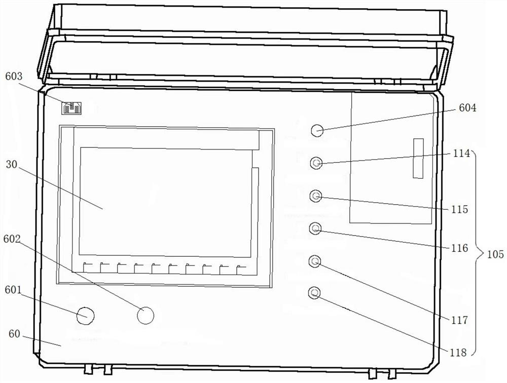
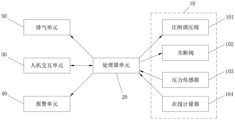
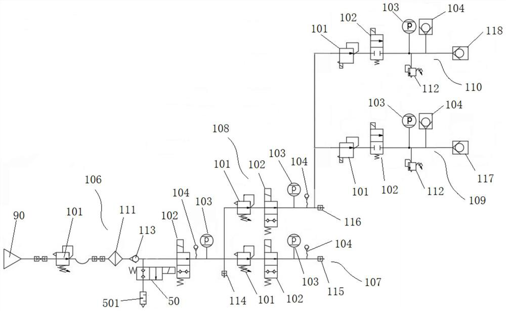
[0038] The present invention will be further described in detail below with reference to the accompanying drawings and specific embodiments.

[0039] As shown in this disclosure and the claims, unless the context clearly dictates otherwise, the words "a," "an," "an," and / or "the" are not intended to be specific in the singular and may include the plural. As used in this disclosure, "first," "second," and similar words do not denote any order, quantity, or importance, but are merely used to distinguish the various components. Likewise, words like "comprising" or "comprising" mean that the elements or things appearing before the word encompass the elements or things recited after the word and their equivalents, but do not exclude other elements or things. Words like "connected" or "connected" are not limited to physical or mechanical connections, but may include electrical connections, whether direct or indirect.

[0040] Figure 1 to Figure 3 An embodiment of an aircraft airt...


PUM


Abstract

The invention discloses an aircraft air tightness test device and an air tightness test method, the device comprises at least two air tightness test modules which are communicated in sequence, an air inlet of the air tightness test module located at the head end is communicated with an air source, and each air tightness test module is provided with a proportional pressure regulating valve, a shut-off valve, a pressure sensor and an air output connector. The proportional pressure regulating valve is used for regulating the air pressure in the air tightness test module, the shut-off valve is used for cutting off or communicating a gas output channel of the proportional pressure regulating valve, the pressure sensor is used for detecting the pressure value of the gas, and the gas output connector is used for being in butt joint with an airplane and outputting the gas. The method comprises the following steps: S1, pressurizing equipment; s2, carrying out pressure maintaining test; and S3, completing the test. According to the invention, at least two air tightness test modules are integrated, a certain air tightness test work can be independently carried out, multiple air tightness test work can be simultaneously carried out, frequent replacement of an air pressure hose and test equipment is not needed, the test time is greatly shortened, and the working efficiency is improved.

Description

technical field [0001] The invention relates to the technical field of aircraft airtightness testing, in particular to an aircraft airtightness testing device and an airtightness testing method. Background technique [0002] In the process of aircraft maintenance, it is necessary to conduct air tightness tests on the aircraft's aerodynamic system, fuel tank pressurization value and pipeline system, wing auxiliary fuel tank pressurization system, cockpit system, and whole aircraft fuel system to ensure that these five tasks are qualified to ensure flight. Safety. [0003] At present, one test equipment can be used for the airtightness test of the cockpit system and the airtightness test of the whole engine fuel system system, and each other airtightness test corresponds to one test equipment respectively, and the four equipments cannot be used in common with each other. Since a test station cannot place multiple test equipment at the same time, and a station has only one air...

Claims


Application Information

Patent Timeline
Patent Type & Authority Applications(China)
IPC IPC(8): G01M3/26B64F5/60
CPCG01M3/26B64F5/60
Inventor 王镇涛莫伟东杨盼郭迎新陈永浩
Owner CHANGSHA 5712 AIRCRAFT IND
Learn More