Atmosphere isolation device for industrial furnace
A technology for isolating devices and industrial furnaces, which is applied in the direction of furnaces, furnace components, and process efficiency improvement. It can solve the problems of high cost, large floor space, and large power consumption, and achieve less electrical equipment and occupy more space. Small, the effect of reducing the use of electric equipment
- Summary
- Abstract
- Description
- Claims
- Application Information
AI Technical Summary
Problems solved by technology
Method used
Image
Examples
Embodiment 1
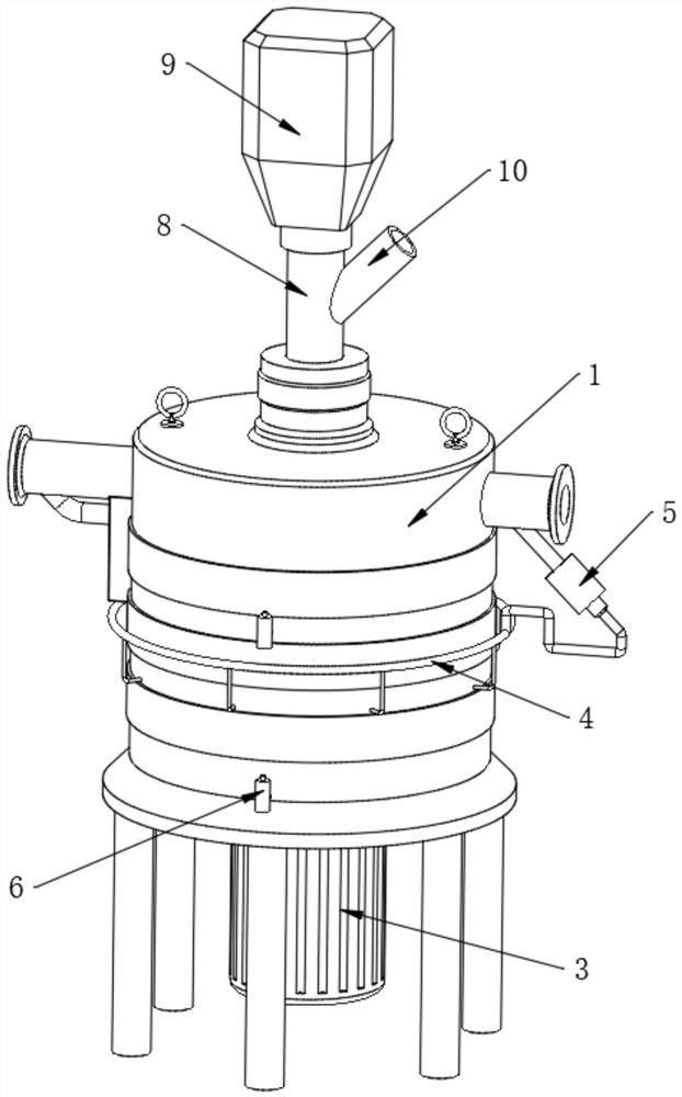
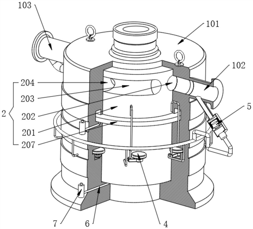
[0038] Refer to the attached Image 6, the isolation outer cylinder 1 also includes an outer cylinder body 101, the top two sides of the outer cylinder body 101 are respectively fixedly connected with an atmosphere inlet channel 102 and an atmosphere discharge channel 103, and a combination cavity 104 is opened inside the outer cylinder body 101, and the outer cylinder body 101 A vent pipe 105 is fixedly connected to the side close to the atmosphere discharge channel 103, and the vent pipe 105 is communicated with the atmosphere discharge channel 103 and the combination cavity 104. The edge of the inner wall of the combined cavity 104 is fixedly provided with a gas permeation cavity 106, and the inner wall of the combined cavity 104 is located in the permeation cavity. A functional cavity 108 is fixedly opened below the air cavity 106 at equal distances, a first oil seal cavity 107 is fixedly opened under the gas permeation cavity 106 , a second sealing cavity 109 is fixedly op...
Embodiment 2
[0048] Refer to the attached Figure 8 The linkage exhaust device 4 also includes a linkage 401. The linkages 401 are respectively fixedly installed inside the functional cavity 108. One end of the linkage 401 is rotatably installed with a fitting wheel 402. When the surfaces are attached to each other, when the inner cylinder 201 is rotated, the attaching wheel 402 will be attached to the outer surface of the inner cylinder 201 and rotate.
[0049] Refer to the attached Figure 9 , the inner end of the linkage 401 is rotatably installed with an inner roller 407, the fitting wheel 402 is fixedly connected with the inner roller 407, the edge of the inner roller 407 is rotatably connected with a deflection rod 408, and the end of the deflection rod 408 is rotated and connected with an inner piston 409. The other end of the outer wall of the actuator 401 is connected with a suction pipe 403 and an exhaust pipe 404 respectively. The inner roller 407 rotates inside the linkage 401...
Embodiment 3
[0055] Refer to the attached Figure 7 One side of the air inlet channel 102 is fixedly connected with an air pressure valve 5. The air pressure valve 5 also includes an air storage pipe 501. One end of the air storage pipe 501 is fixedly provided with an elastic air bag 506. The end of the connecting pipe 406 is connected to the elastic air bag 506. The air storage pipe 501 The other end of the gas storage pipe 501 is fixedly connected with an inclined conduit 502, and the inner diameter of the gas storage pipe 501 is larger than the inner diameter of the inclined conduit 502. The inclined conduit 502 is connected to the atmosphere inlet passage 102, and the inclined conduit 502 and the atmosphere inlet passage 102 are close to the outer cylinder 101. The intersection angle on one side is an obtuse angle, a vent 503 is fixed inside the gas storage tube 501, and a gas port plug 504 is movably provided on the side of the gas storage tube 501 close to the inclined conduit 502, an...
PUM
 Abstract
Description
Claims
Application Information
 - R&D
- Intellectual Property
- Life Sciences
- Materials
- Tech Scout
- Unparalleled Data Quality
- Higher Quality Content
- 60% Fewer Hallucinations
Browse by: Latest US Patents, China's latest patents, Technical Efficacy Thesaurus, Application Domain, Technology Topic, Popular Technical Reports.
© 2025 PatSnap. All rights reserved.Legal|Privacy policy|Modern Slavery Act Transparency Statement|Sitemap|About US| Contact US: help@patsnap.com


