


Quick Research
Generate reliable direction feasibility study reports for your R&D in just a few steps.

Technical Q&A
Discover and master advanced knowledge NOW. Basics, ideas, possibilities, all at once.

Find Solutions
As an expert in R&D theories, this can generate solutions to your technical problems instantly.

Evaluate Feasibility
Analyze your overall solution with one click, know your potential R&D risks in advance.

Monitor Landscape
Get weekly tech updates, stay abreast of the latest tech innovations and key insights.
Flue gas evaporation device for high-concentration waste water boiler of power station
A boiler flue gas and evaporation device technology, applied in energy wastewater treatment, general water supply conservation, heating water/sewage treatment, etc., can solve the problem that the waste heat of concentrated wastewater cannot be recycled, resources cannot be effectively used, and the evaporation effect is not ideal and other issues to achieve the effect of improving resource utilization, reducing heat loss, and improving utilization
- Summary
- Abstract
- Description
- Claims
- Application Information
AI Technical Summary
Problems solved by technology
Method used
Image

Examples
Embodiment 1
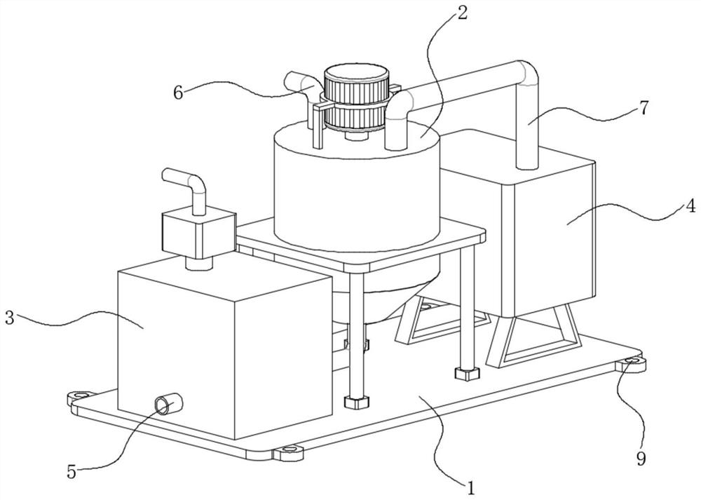
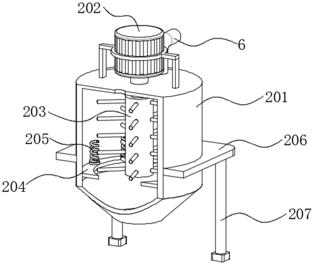
[0026] see Figure 1 to Figure 5 , a power plant high-concentration waste water boiler flue gas evaporation device, including a base 1, an evaporation mechanism 2 is arranged above the base 1, the evaporation mechanism 2 includes an evaporation boiler 201, the evaporation boiler 201 is communicated with the waste water injection pipe 6, and the evaporation boiler 201 A motor 202 is installed on the upper surface, the output end of the motor 202 is rotatably connected to the upper surface of the evaporation boiler 201, and the output end of the motor 202 extends to the interior of the evaporation boiler 201, and the output end of the motor 202 is fixedly connected with a stirring shaft 203. The stirring shaft The outer surface of 203 is provided with round rods arranged at equal distances. Through the rotation of the stirring shaft 203, the wastewater is stirred and treated under the action of the round rods, so as to improve the evaporation efficiency.
[0027] A support plate...
Embodiment 2
[0029] Compared with Example 1, on the basis of Example 1,
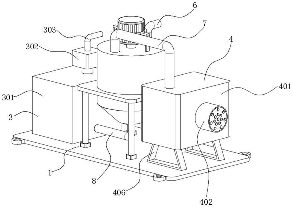
[0030] A recovery mechanism 3 is arranged above the base 1, and the recovery mechanism 3 includes a heat preservation box 301. The heat preservation box 301 is communicated with the drain pipe 5. The upper surface of the heat preservation box 301 is communicated with an exhaust pump 302, and the upper surface of the exhaust pump 302 is communicated with an exhaust gas. Pipe 303, the inner wall of the incubator 301 is fixedly connected with a heat insulation board 304, the inside of the incubator 301 is installed with a heat exchange conduit 305, the drain pipe 5 is communicated with the heat exchange conduit 305 inside the incubator 301, and the heat exchange conduit 305 belongs to the current In the prior art, the heat contained in the waste water can be released through the heat exchange conduit 305 and stored in the incubator 301 .
Embodiment 3
[0032] Compared with Example 2, on the basis of Example 2,
[0033] A treatment mechanism 4 is arranged above the base 1, and the treatment mechanism 4 includes a treatment box 401. The treatment box 401 belongs to the prior art. Through the treatment box 401, the evaporated flue gas can be treated, and then discharged into the atmosphere to avoid pollution. Atmosphere, the outer surface of the processing box 401 is communicated with an exhaust cylinder 402, the inner wall of the exhaust cylinder 402 is fixedly connected with a bracket 403, an exhaust fan 404 is installed on the outer surface of the bracket 403, and an odor elimination plate is installed on the inner wall of the exhaust cylinder 402. 405. Two T-shaped frames 406 are fixedly connected to the bottom surface of the processing box 401. The bottom surfaces of the two T-shaped frames 406 are fixedly connected to the upper surface of the base 1. The power of the exhaust fan 404 can be adjusted. When there is a lot of...
PUM
 Abstract
Description
Claims
Application Information
 - R&D Engineer
- R&D Manager
- IP Professional
- Industry Leading Data Capabilities
- Powerful AI technology
- Patent DNA Extraction
Browse by: Latest US Patents, China's latest patents, Technical Efficacy Thesaurus, Application Domain, Technology Topic, Popular Technical Reports.
© 2024 PatSnap. All rights reserved.Legal|Privacy policy|Modern Slavery Act Transparency Statement|Sitemap|About US| Contact US: help@patsnap.com