Medical image classification system based on magnetic resonance
A medical imaging and classification system technology, which is applied in thin material processing, transportation and packaging, stacking receiving devices, etc., can solve the problems that the overall quality of medical imaging cannot be guaranteed, and the automatic stacking and classification of medical imaging cannot be realized, so as to avoid Squeeze interference, facilitate classification and induction, and reduce shaking effects
- Summary
- Abstract
- Description
- Claims
- Application Information
AI Technical Summary
Problems solved by technology
Method used
Image
Examples
Embodiment 1
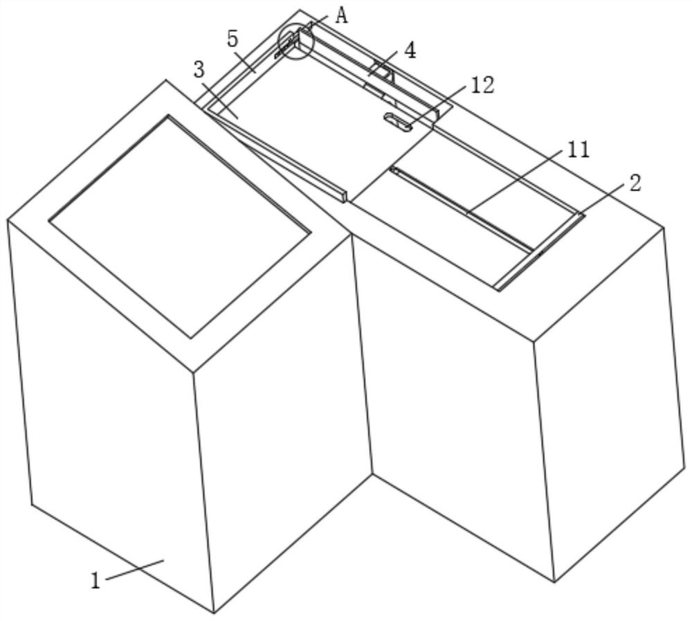
[0033] see figure 1 , Figure 3 to Figure 5 , the embodiment of the present invention provides a classification system for medical imaging based on magnetic resonance: including a workbench 1, the workbench 1 is a place for medical staff to receive and classify medical imaging films, which is an existing mature technology, and will not be described in detail here. The upper surface of the worktable 1 is provided with a placement slot, and the inside of the placement slot is fixedly installed with a drive assembly 2 for pushing medical imaging films, and the interior of the worktable 1 is movably provided with a partition 3 for receiving medical imaging films, and the worktable 1. The position corresponding to the partition 3 is an open design, the partition 3 is inclined to the side away from the drive assembly 2, the upper surface of the partition 3 is fixedly installed with an L-shaped frame 5, and the two sides of the L-shaped frame 5 correspond to the partition The back s...
Embodiment 2
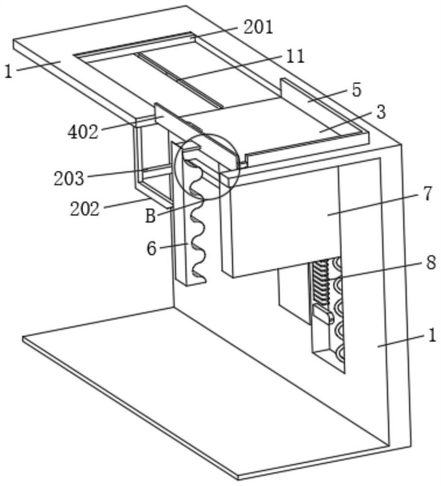
[0037] see figure 1 , Figure 3 to Figure 10 , on the basis of Embodiment 1, the drive assembly 2 includes an electric push rod (not shown in the figure) that is fixedly connected with the placement groove, and the movable end of the electric push rod is fixedly connected with a push plate 201 for pushing medical image films, and pushes The bottom of the board 201 is fixedly installed with a guide rod 202 corresponding to the position of the card slot 703. The card slot 703 is designed in a zigzag shape, and the corresponding end of the guide rod 202 is set to be inclined towards the same slope as the card slot 703, and both face the upper right. tilt( Figure 5 Viewing angle), so that when the inclined surface of the guide rod 202 fits with the card slot 703, the card slot 703 can be squeezed to make it tend to move downward, so that the support assembly 7 has a downward tendency to move; the surface of the guide rod 202 The insertion rod 203 corresponding to the position o...
Embodiment 3
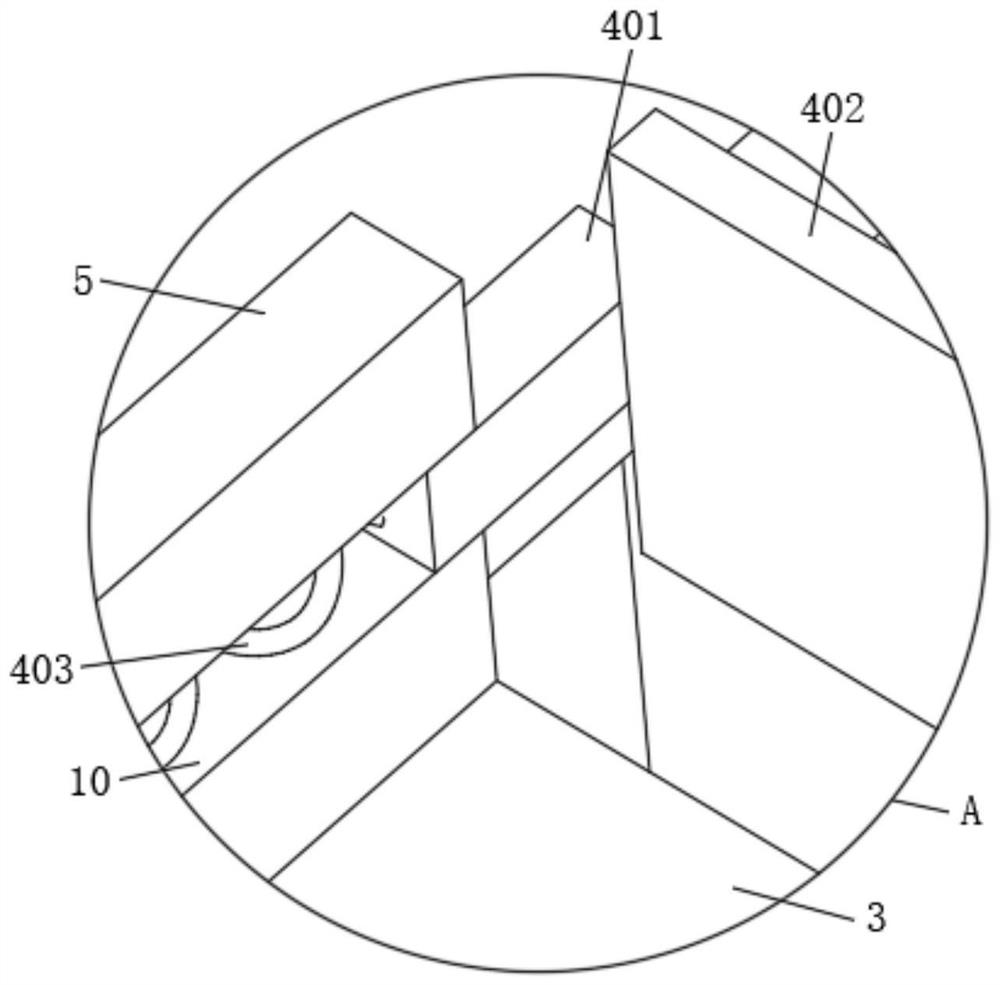
[0046] see Figure 1 to Figure 10, on the basis of the second embodiment, the L-shaped frame 5 is provided with a chute 10 inside, the lamination component 4 is slidably installed inside the chute 10, and the worktable 1 is fixedly installed with the lamination component 4 movably attached. Under the action of the adjusting assembly 6, the fitting assembly 4 cooperates with the L-shaped frame 5 to complete the alignment of the medical image film; the surface of the partition 3 is provided with a through hole 12 for fingers to pass through.
[0047] The fitting assembly 4 includes a short rod 401 slidably matched with the chute 10 , the surface of the short rod 401 is fixedly mounted with a side plate 402 for aligning medical image films, and the end of the short rod 401 is fixed between the groove wall of the chute 10 A first spring 403 is installed. Under the action of the first spring 403, both the short rod 401 and the side plate 402 tend to move away from the partition 3; ...
PUM
 Abstract
Description
Claims
Application Information
 - R&D
- Intellectual Property
- Life Sciences
- Materials
- Tech Scout
- Unparalleled Data Quality
- Higher Quality Content
- 60% Fewer Hallucinations
Browse by: Latest US Patents, China's latest patents, Technical Efficacy Thesaurus, Application Domain, Technology Topic, Popular Technical Reports.
© 2025 PatSnap. All rights reserved.Legal|Privacy policy|Modern Slavery Act Transparency Statement|Sitemap|About US| Contact US: help@patsnap.com


