
Tire mold laser cleaning equipment

A technology for laser cleaning and tire molds, applied to tires, household appliances, and other household appliances, can solve problems such as low work efficiency and achieve the effect of improving stability

Pending Publication Date: 2022-08-09
江西迪亚特自动化设备有限公司
View PDF1 Cites 2 Cited by
  • Summary
  • Abstract
  • Description
  • Claims
  • Application Information

AI Technical Summary

Problems solved by technology

[0005] In order to overcome the shortcoming that people need to adjust the position of the metal and the work efficiency will be relatively low, the technical problem to be solved is to provide a tire mold laser cleaning equipment that can automatically center the tire mold and improve work efficiency.

Method used


Image

  • Tire mold laser cleaning equipment
  • Tire mold laser cleaning equipment
  • Tire mold laser cleaning equipment

Examples


Embodiment 1

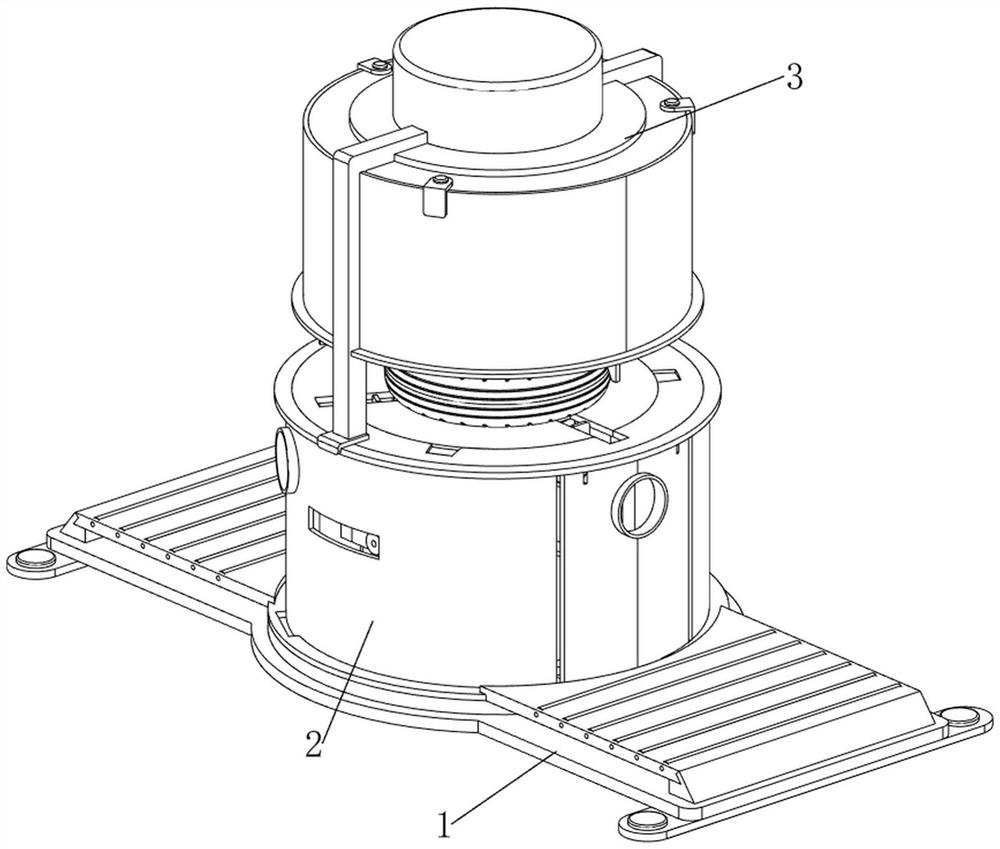
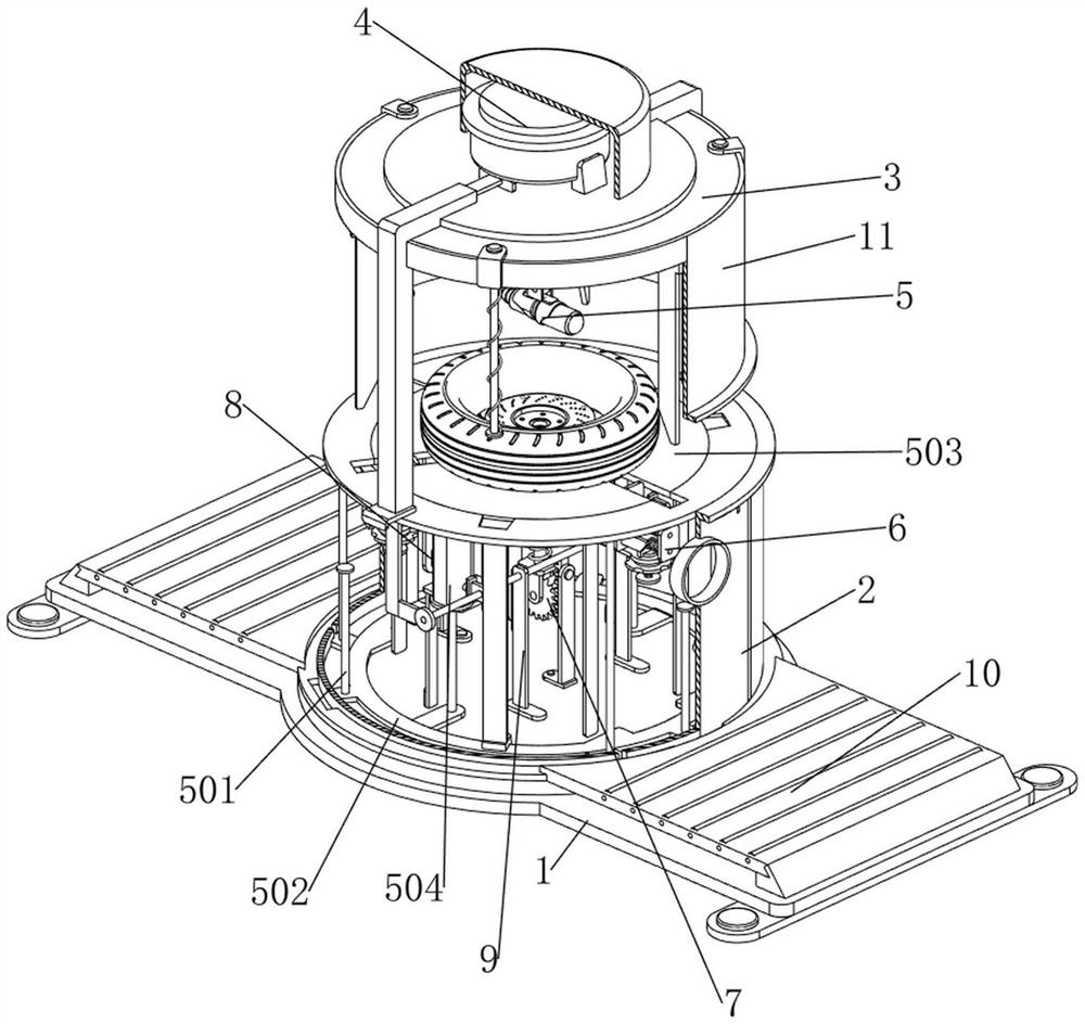
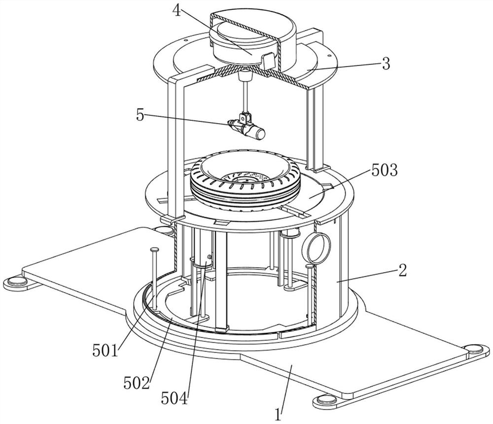
[0037] A tire mold laser cleaning equipment, such as Figure 1-3 As shown, it includes a bottom plate 1, a connecting lower frame 2, a connecting assembly 3, a motor 4, a laser 5, a first connecting rod 501, a sliding frame 502, a carrying plate 503, a cylinder 504, a centering mechanism 6 and a lifting mechanism 7, the bottom plate 1. The middle part is connected with the lower frame 2 by bolts, the top of the lower frame 2 is connected by bolts with the connection component 3, the middle of the connection component 3 is connected with the motor 4 by bolts, and the lower part of the output shaft of the motor 4 is connected with the laser instrument 5 by bolts, The laser instrument 5 can perform laser cleaning on the tire mold. The top of the bottom plate 1 is uniformly welded with first connecting rods 501 along the circumferential direction. The sliding frame 502, the sliding frame 502 can slide up and down on the first connecting rod 501, the upper part of the sliding frame...

Embodiment 2

[0042] On the basis of Example 1, as figure 2 , Figure 9 and Figure 10 As shown, it also includes a stabilization mechanism 8, which can clamp the connection plate 63, thereby improving the stability of the connection plate 63. The stabilization mechanism 8 includes an unlocking driving plate 81, a second sliding sleeve plate 82, a first clamping plate 83, an inclined surface The driving plate 84 and the third spring 85, the unlocking driving plate 81 is connected to the top left side of the bottom plate 1 by bolts, the second sliding sleeve plate 82 is connected to the bottom left side of the bearing plate 503 by bolts, and the second sliding sleeve plate 82 is slidably connected There is a first card plate 83, the first card plate 83 can slide on the second sliding sleeve plate 82, when the connecting plate 63 moves upward and contacts the first card plate 83, it will push the first card plate 83 to the left, and the first card plate 83 is pushed to the left. The left s...


PUM


Abstract

The invention relates to cleaning equipment, in particular to laser cleaning equipment for a tire mold. According to the laser cleaning equipment for the tire mold, the tire mold can be automatically stirred and centered, and the working efficiency is improved. According to the technical scheme, the tire mold laser cleaning equipment comprises a bottom plate, a connecting lower frame, a connecting assembly, a motor, a laser instrument and the like, the connecting lower frame is connected to the middle of the bottom plate through bolts, the connecting assembly is connected to the top of the connecting lower frame through bolts, and the motor is connected to the middle in the connecting assembly through bolts; the lower portion of an output shaft of the motor is connected with a laser through bolts. When an extrusion plate moves upwards to be in contact with a slope rod, the extrusion plate can move towards the inner side, and in the upward moving process of a tire mold, the extrusion plate automatically centers the tire mold.

Description

technical field [0001] The invention relates to cleaning equipment, in particular to a tire mold laser cleaning equipment. Background technique [0002] Now when making tires, the tire molds are usually cleaned. There are many cleaning methods, such as: hand-held water pipes to rinse the tire molds or use a vibration device to vibrate the water to clean the tire molds. Although these methods can achieve cleaning However, the cleaning effect is very general. Now laser cleaning is a more advanced method, and the cleaning effect will be better. [0003] Patent Publication No. CN205732154U A large-format laser cleaning machine includes a workbench, and a conveyor belt driven by a stepping motor is arranged on the workbench along the length direction of the workbench. There is a lifting mechanism on the frame, and two ends of a lifting beam arranged along the width direction of the worktable are respectively connected with the lifting mechanism. A number of laser cleaners are ar...

Claims


Application Information

Patent Timeline
IPC IPC(8): B29C33/72B08B7/00B29L30/00
CPCB29C33/72B08B7/0042B29L2030/00Y02W30/62
Inventor 黄良岳杨风坤黎国强
Owner 江西迪亚特自动化设备有限公司
Learn More