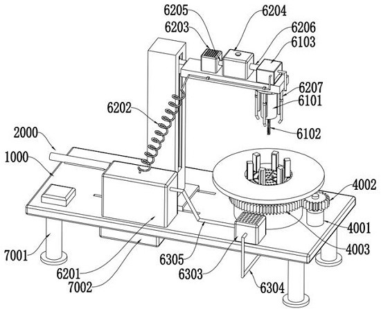
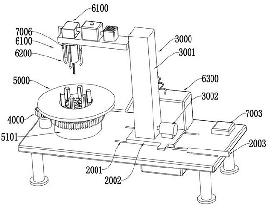
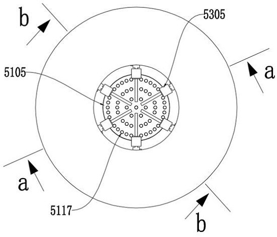
Passive self-alignment type drilling and clamping equipment for thick and heavy stainless steel circular plate

A clamping equipment, passive technology, applied in the direction of drilling/drilling equipment, boring/drilling, metal processing equipment, etc., can solve the problems of low efficiency, waste, pressure reduction, etc., and achieve the goal of ensuring accuracy Effect

Inactive Publication Date: 2022-08-05
泰州万鼎电气有限公司
View PDF10 Cites 0 Cited by
  • Summary
  • Abstract
  • Description
  • Claims
  • Application Information

AI Technical Summary

Problems solved by technology

[0004] In view of the above situation, in order to overcome the defects of the prior art, the present invention provides a passive self-centering equipment for drilling and clamping thick and heavy stainless steel circular plates. For thick and heavy circular stainless steel plates, workers need to manually perform centering operations before drilling and the technical problems of time-consuming, labor-intensive and poor accuracy caused by the clamping operation. Without any sensors and driving sources, this solution skillfully utilizes the gravity of the thick and heavy circular stainless steel plate itself, and is placed on the circular stainless steel plate. After receiving the upper surface of the plate, the gravity of the circular stainless steel plate itself is automatically converted into the power source for the centering operation and clamping operation through the passive self-fixing clamping mechanism, and the automatic alignment is realized only through a simple mechanical structure. The technical effect of the centering operation and clamping operation of the circular stainless steel plate does not require workers to manually perform the centering operation and clamping operation on the heavy stainless steel plate, which not only saves time and effort, but also ensures the accuracy of the centering operation
[0005] Aiming at the contradictory problem of neither too much cutting fluid (watering too much cutting fluid can ensure the cooling effect, but it will cause waste) nor too little (when the cutting fluid is too little, it needs to stop frequently to apply cutting fluid, which is time-consuming, laborious and inefficient). , this solution creatively introduces the Venturi effect. When the gas flows through the pipe whose diameter changes from thick to thin, the flow velocity of the gas increases and the pressure decreases, thereby forming a vacuum zone at the end of the ejection cavity close to the acceleration cavity, and at the end of the vacuum zone Under the action of negative pressure suction, the cutting fluid is sucked into the injection chamber. At this time, driven by the high-speed flowing compressed air, the cutting fluid is sprayed to the designated area that needs to be cooled. When the drilling speed is faster, the drill bit and The greater the calorific value of the contact position of the stainless steel circular plate, the more cutting fluid is sprayed. When the drilling speed is slower, the calorific value of the contact position between the drill bit and the stainless steel circular plate is smaller, and the less cutting fluid is sprayed. This scheme uses centrifugal The combined use of the open and close cutting fluid control drilling assembly and the cutting fluid injection assembly cleverly introduces the effect of centrifugal force. Only through a simple mechanical structure and without any sensors and detection elements, this scheme can be used when drilling It can automatically spray an appropriate amount of cutting fluid according to the calorific value without spraying excess cutting fluid, which ensures a good cooling effect and avoids the waste of cutting fluid

Method used


Image

  • Passive self-alignment type drilling and clamping equipment for thick and heavy stainless steel circular plate
  • Passive self-alignment type drilling and clamping equipment for thick and heavy stainless steel circular plate
  • Passive self-alignment type drilling and clamping equipment for thick and heavy stainless steel circular plate

Examples


Embodiment Construction

[0049] The technical solutions in the embodiments of the present invention will be clearly and completely described below with reference to the accompanying drawings in the embodiments of the present invention. Obviously, the described embodiments are only a part of the embodiments of the present invention, rather than all the embodiments; based on the The embodiments of the present invention, and all other embodiments obtained by those of ordinary skill in the art without creative work, fall within the protection scope of the present invention.

[0050] In the description of the present invention, it should be understood that the terms "upper", "lower", "front", "rear", "left", "right", "top", "bottom", "inside", " “Outside” and other indications of orientation or positional relationship are based on the orientation or positional relationship shown in the accompanying drawings, which are only for the convenience of describing the present invention and simplifying the descripti...


PUM


Abstract

The invention discloses passive self-alignment type thick and heavy stainless steel circular plate drilling clamping equipment which comprises a workbench, a translation assembly, a lifting assembly, a rotating assembly, a passive self-fixing clamping mechanism and a centrifugal drilling jet cooling mechanism, an annular rotating groove and a communicating rotating groove are formed in the workbench, the translation assembly is arranged on the top wall of the workbench, and the lifting assembly is arranged on the top wall of the workbench. The lifting assembly is arranged on the translation assembly, a fixing plate is arranged on the lifting assembly, and the passive type self-fixing clamping mechanism is rotationally arranged on the annular rotating groove and the communicating rotating groove. The invention belongs to the technical field of stainless steel circular plate machining equipment, and particularly relates to passive self-alignment type drilling and clamping equipment for a thick and heavy stainless steel circular plate. The technical problems that in the prior art, the contradictory problem that cutting fluid cannot be too much or too little is difficult to solve, and time and labor are wasted and accuracy is poor due to the fact that a heavy circular stainless steel plate needs to be manually centered and clamped by workers before punching are solved.

Description

technical field [0001] The invention belongs to the technical field of stainless steel circular plate processing equipment, in particular to passive self-centering heavy stainless steel circular plate drilling and clamping equipment. Background technique [0002] At present, before punching a large and heavy circular stainless steel plate, in order to ensure the accuracy of punching, the circular stainless steel plate needs to be centered. The relative displacement affects the accuracy of punching, and the circular stainless steel plate needs to be fixed on the workbench. In the prior art, in order to realize the centering operation, the workers mostly adjust the position of the stainless steel plate by manually pushing and pulling the stainless steel plate. , After the adjustment is completed, the worker clamps and fixes the circular stainless steel plate by manually adjusting the clamping mechanism. In this way, the worker needs to adjust it repeatedly. Because the circula...

Claims


Application Information

Patent Timeline
Patent Type & Authority Applications(China)
IPC IPC(8): B23B41/00B23Q1/25B23Q3/06B23Q11/10
CPCB23B41/00B23Q1/25B23Q3/062B23Q11/10B23Q11/1069Y02P70/10
Inventor 周桂凤
Owner 泰州万鼎电气有限公司
Why Eureka
Try Eureka