
Electric wire and cable powder coating device

A powder coating, wire and cable technology, applied in the manufacture of cables/conductors, insulation of conductors/cables, circuits, etc., can solve the problems that powder cannot be completely absorbed, talcum powder loses fluidity, and core wires stick to core wires. To achieve the effect of eliminating internal agglomeration, good fluidity and avoiding sticking

Pending Publication Date: 2022-07-29
WUXI HUAHAO ELECTRIC
View PDF0 Cites 0 Cited by
  • Summary
  • Abstract
  • Description
  • Claims
  • Application Information

AI Technical Summary

Problems solved by technology

[0005] However, there are still some problems in this powder passing device at present. Because the talcum powder is pushed in one direction, the talcum powder is accumulated at one end of the powder box, which will not only cause the talcum powder to easily overflow from the line hole at the end of the powder box, and affect the working environment, and also cause local talcum powder to lose fluidity, resulting in agglomeration inside the powder pile and increasing the energy consumption of the motor
[0006] In addition, for the ply multi-core conductor, since there are gaps between the core wires, after the conductor is coated with talc powder, the talcum powder in the gap is also easily shaken off during the movement of the conductor, resulting in that the powder cannot be completely adsorbed on the core. On the wire, resulting in partial adhesion between the core wire and the core wire after the cable is extruded

Method used


Image

  • Electric wire and cable powder coating device
  • Electric wire and cable powder coating device
  • Electric wire and cable powder coating device

Examples


Embodiment Construction

[0023] Specific embodiments of the present invention will be described in detail below with reference to the accompanying drawings.

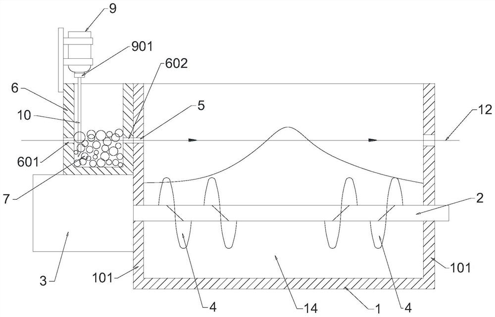
[0024] like figure 1 The above-mentioned powder coating device for electric wires and cables includes a powder box 1, and a rotary shaft 2 is horizontally arranged in the powder box 1. One end of the powder box 1 protrudes out of the powder box 1 through the end plate 101 and is connected with the drive motor 3 in a driving manner. The rotating shaft 2 located in the powder box 1 is fixedly sleeved with two spiral blades 4 with opposite directions of rotation. 2 are arranged in sequence in the axial direction, and the end plates 101 at both ends of the powder box 1 are respectively provided with coaxially arranged wire-passing holes 5 .

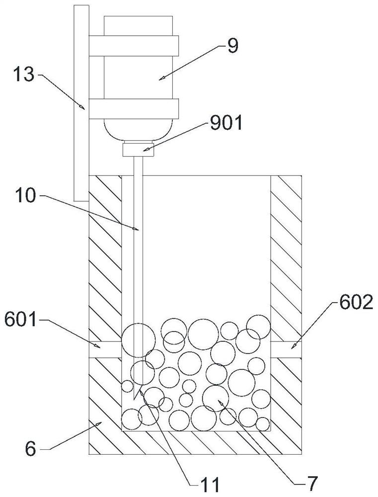
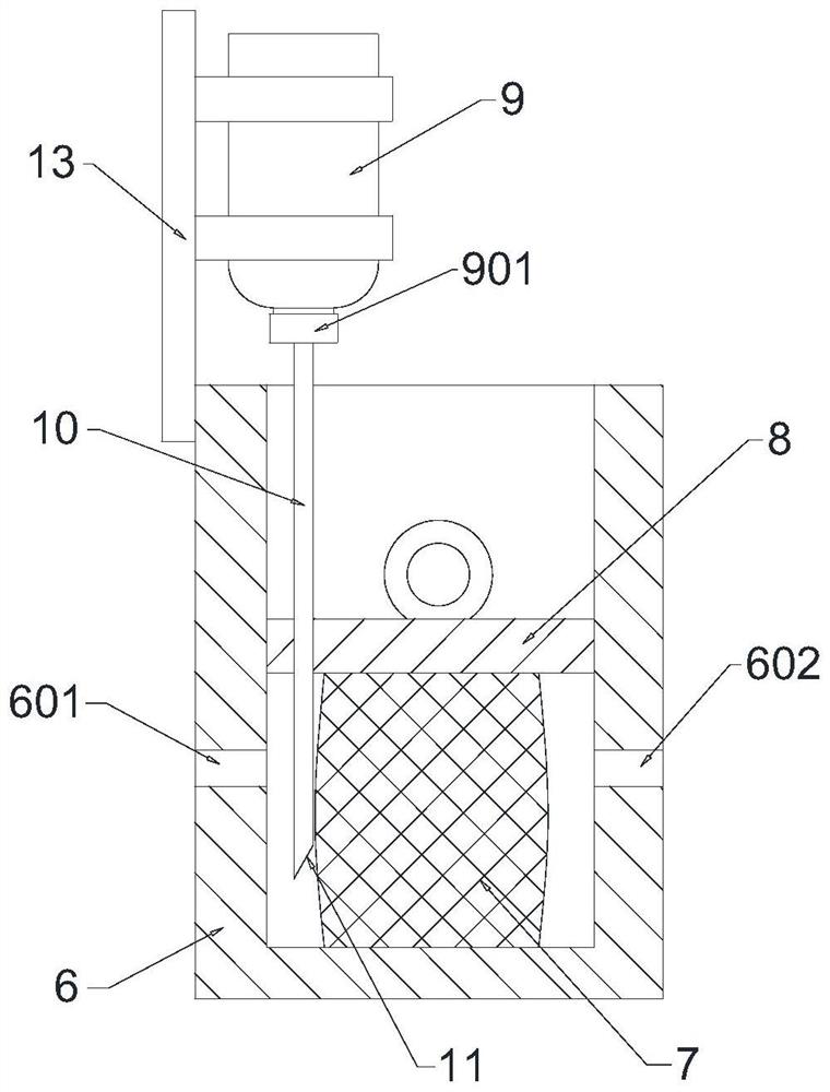
[0025] An infiltration box 6 is connected to the outer wall of the upstream end plate 101 of the powder box 1. The infiltration box 6 is provided with an infiltration liquid carrier 7. The upstream and downstr...


PUM


Abstract

The invention relates to an electric wire and cable powder coating device which comprises a powder box and is characterized in that a rotating shaft is horizontally arranged in the powder box, the two ends of the rotating shaft are rotationally connected to end plates at the two ends of the powder box respectively, and one end of the rotating shaft penetrates through the end plates, extends out of the powder box and is in transmission connection with a driving motor; two spiral blades with opposite rotating directions are fixedly sleeved on the rotating shaft in the powder box, the two spiral blades are sequentially arranged along the axial direction of the rotating shaft, and coaxial wire passing holes are respectively formed in end plates at two ends of the powder box. The two spiral blades with opposite rotating directions are arranged on the rotating shaft, so that when the rotating shaft rotates, the two spiral blades push talcum powder to move oppositely, a powder pile is formed in the middle of the powder box, and the talcum powder can be effectively prevented from overflowing.

Description

technical field [0001] The invention belongs to the technical field of wire and cable processing, and in particular relates to a wire and cable powder coating device. Background technique [0002] The manufacture of wires and cables adopts the continuous superposition and combined production method. Starting from the conductor processing, the wire and cable products are made by superimposing insulation, shielding, cabling, sheathing, etc. on the periphery of the conductor. The heated hot-melt / thermosetting material is melted and wrapped on the cable core, which can easily lead to adhesion between the insulation of the cable core, between the insulation and the sheath, and the adhered core and sheath will be cut later. It is difficult to separate when peeling, which can easily lead to tearing of the insulating layer and exposed copper wires, resulting in potential safety hazards. [0003] In order to solve the above technical problems, the current solution is to coat the sur...

Claims


Application Information

Patent Timeline
Patent Type & Authority Applications(China)
IPC IPC(8): H01B13/22H01B13/24H01B13/14
CPCH01B13/22H01B13/24H01B13/227H01B13/145
Inventor 朱旻栎娄宏超黄本雷
Owner WUXI HUAHAO ELECTRIC
Learn More