
Method and system for evaluating vibration of main shaft

An evaluation method and spindle technology, applied in the testing of mechanical components, testing of machine/structural components, measuring devices, etc., can solve the problems of inconsistency in judgment errors, selection of spindles, and cumbersome detection process, etc., to improve consistency and stability Sexuality, avoiding waste of resources, and reducing manufacturing costs

Pending Publication Date: 2022-07-29
北京精雕精密机械制造有限公司
View PDF0 Cites 0 Cited by
  • Summary
  • Abstract
  • Description
  • Claims
  • Application Information

AI Technical Summary

Problems solved by technology

Since the existing vibration detection instruments or systems only have the functions of signal acquisition and data processing, and do not have the function of automatic evaluation, only the final detection data can be given, and automatic evaluation cannot be performed, and human judgment is required. Experience requirements are very high, and problems such as misjudgment and inconsistency are prone to occur, thereby affecting the use effect of CNC machine tools; on the other hand, human judgment can only be evaluated at a limited number of speed points, and it is impossible to achieve a comprehensive evaluation of the entire speed range. analysis, and can only judge whether it is qualified or not, it is impossible to rate the vibration of the spindle, and then it is impossible to select a matching spindle according to the requirements of the machine tool, which is likely to cause waste of resources
In addition, the existing evaluation methods still have problems such as cumbersome detection process and difficult operation.

Method used


Image

  • Method and system for evaluating vibration of main shaft
  • Method and system for evaluating vibration of main shaft
  • Method and system for evaluating vibration of main shaft

Examples


Embodiment Construction

[0043] The present invention will be described in further detail below with reference to the accompanying drawings and specific embodiments.

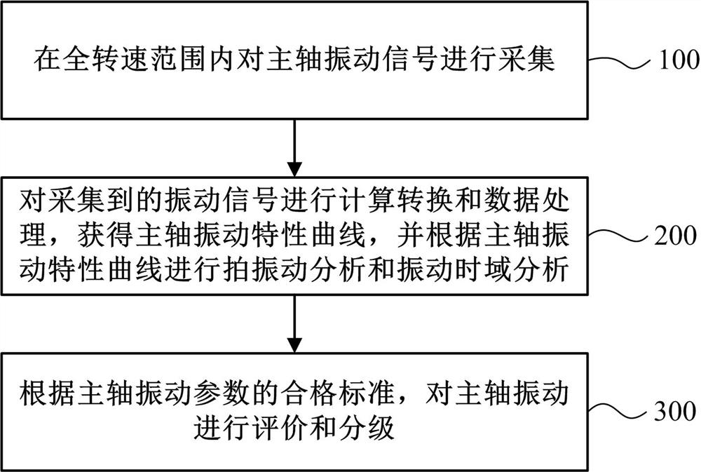
[0044] like figure 1 As shown, a method for evaluating the vibration of a main shaft of the present invention includes:

[0045] Step 100, collecting the vibration signal of the main shaft within the full rotational speed range;

[0046] Step 200, performing calculation conversion and data processing on the collected vibration signal, obtaining a main shaft vibration characteristic curve, and performing beat vibration analysis and vibration time domain analysis according to the main shaft vibration characteristic curve;

[0047] Wherein, the main shaft vibration characteristic curve includes a rotation speed-vibration acceleration curve, a rotation speed-vibration speed curve, a rotation speed-vibration factor curve, a time-vibration acceleration curve, and a time-vibration speed curve;

[0048] The data processing of vibration signals ...


PUM


Abstract

The invention belongs to the field of mechanical performance detection, and particularly relates to a main shaft vibration evaluation method and system. Main shaft vibration parameters including vibration acceleration, vibration speed, vibration factors, beat vibration and vibration time domain are obtained by detecting and analyzing main shaft vibration in a full rotation speed range; and respectively and automatically comparing and analyzing with respective qualified standards to obtain an evaluation or rating result of the vibration parameters of each main shaft. And automatically judging the vibration grade of the main shaft according to the evaluation or rating result of each main shaft vibration parameter. According to the invention, not only can automatic detection and analysis of spindle vibration be realized, but also automatic evaluation and grading can be carried out according to the detection and analysis result, no human participation is needed, the operation is simple, the analysis is comprehensive, and the reliability is high.

Description

technical field [0001] The invention belongs to the field of mechanical performance detection, and particularly relates to a method and system for evaluating the vibration of a main shaft. Background technique [0002] As one of the core functional components of CNC machine tools and an important support for advanced processing technologies such as high-speed machining and high-precision machining, the vibration generated by the electric spindle under high-speed operation will be transmitted to the CNC machine tool, thereby reducing the dynamic accuracy of the machine tool and the machining process. The surface quality of the parts will also have a very negative impact on the production efficiency and tool life. Therefore, before the CNC machine tool is assembled, it is an indispensable link to evaluate whether the electric spindle meets the assembly requirements. [0003] The existing spindle vibration evaluation method is to perform vibration detection on the spindle throu...

Claims


Application Information

Patent Timeline
IPC IPC(8): G01H17/00G01M13/00
CPCG01H17/00G01M13/00
Inventor 郭学宏崔立英吴爱军张乐顾鑫王世杰
Owner 北京精雕精密机械制造有限公司
Learn More