Weather-proof air flow sensor for monitoring air inlet temperature and process of weather-proof air flow sensor

A technology of intake air temperature and air flow, applied in the application of thermometers, volume/mass flow generated by electromagnetic effects, thermometers, etc., can solve the problem of not considering ambient temperature monitoring data, air flow detection data distortion, poor component stability, etc. problem, to achieve the effect of improving stirring efficiency, improving stirring effect, and improving corrosion resistance.

Pending Publication Date: 2022-07-29
温州荣际新能源有限公司
View PDF7 Cites 0 Cited by
  • Summary
  • Abstract
  • Description
  • Claims
  • Application Information

AI Technical Summary

Problems solved by technology

It converts the inhaled air flow into an electrical signal and sends it to the electronic control unit (ECU), as one of the basic signals for determining fuel injection. At present, the air flow sensor is a key component in the electronic control system of the automobile engine. Its function is to use To monitor the intake air mass flow of the engine, the current working environment in the prior art does not consider whether the ambient temperature has an impact on the monitoring data. In this way, the detected data has a large error, and the components are affected by the temperature of the air duct, resulting in poor stability. The component circuit affects the hot film component on the wind measuring component placement rack, which further causes the distortion of the air flow detection data

Method used

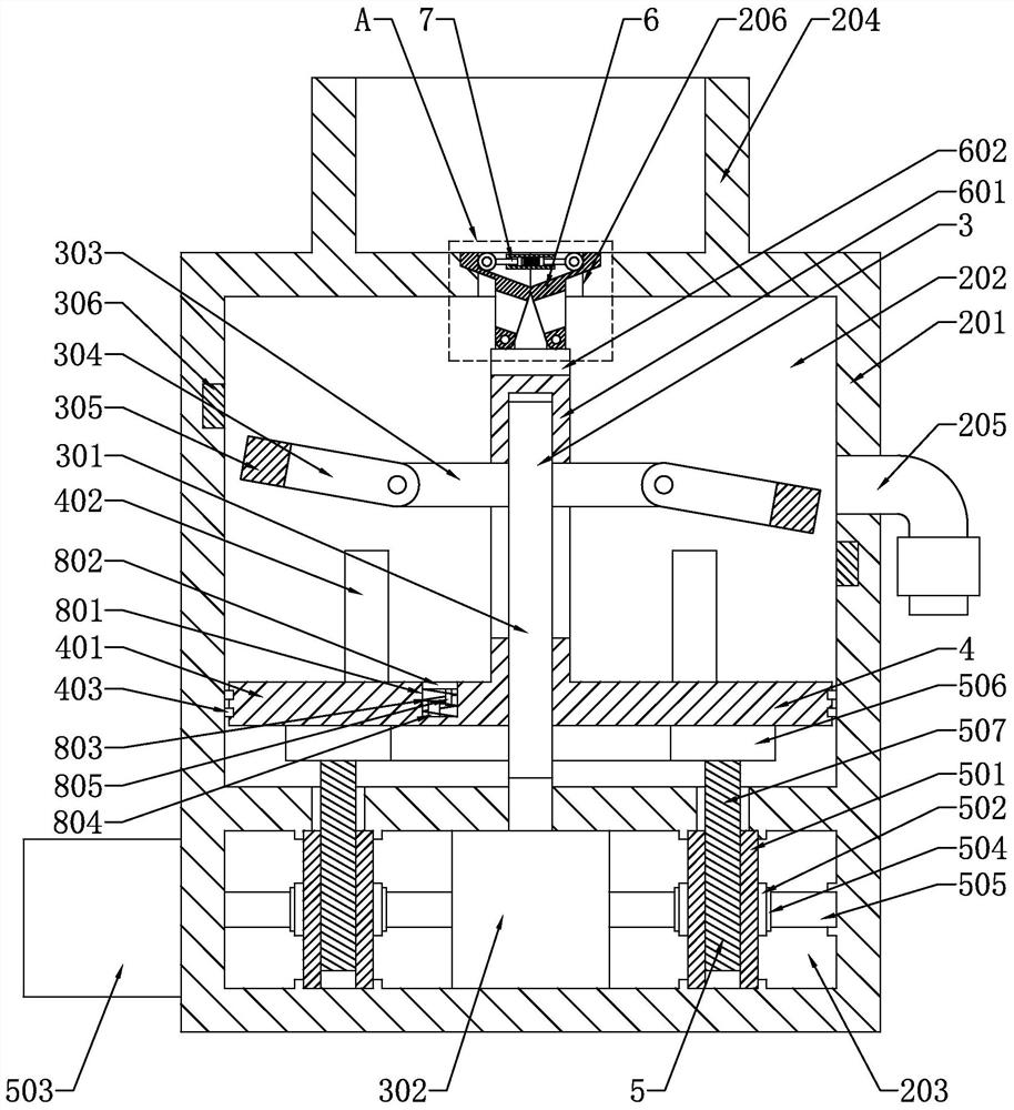
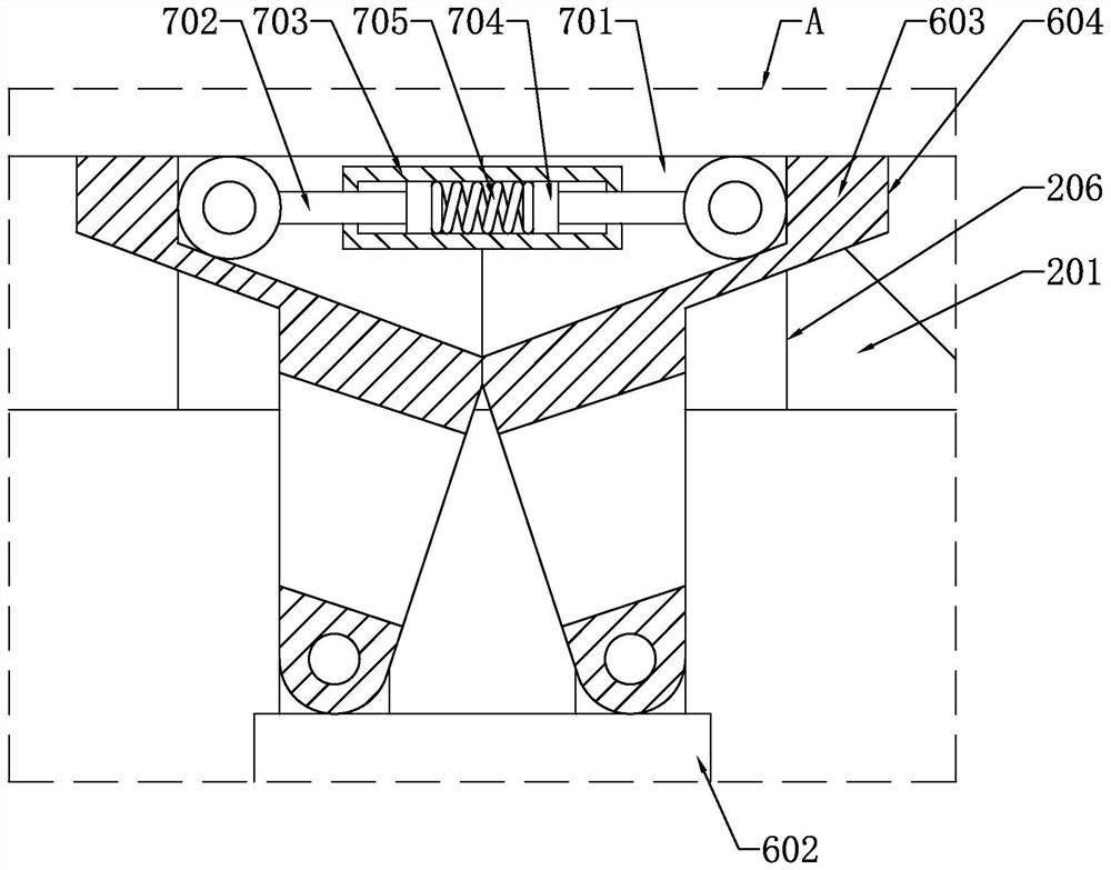

Image

  • Weather-proof air flow sensor for monitoring air inlet temperature and process of weather-proof air flow sensor
  • Weather-proof air flow sensor for monitoring air inlet temperature and process of weather-proof air flow sensor
  • Weather-proof air flow sensor for monitoring air inlet temperature and process of weather-proof air flow sensor

Examples


Embodiment Construction

[0070] The technical solutions in the embodiments of the present application will be clearly described below with reference to the accompanying drawings in the embodiments of the present application. Obviously, the described embodiments are part of the embodiments of the present application, but not all of the embodiments. Based on the embodiments in this application, all other embodiments obtained by those of ordinary skill in the art fall within the protection scope of this application.

[0071] The terms "first", "second" and the like in the description and claims of the present application are used to distinguish similar objects, and are not used to describe a specific order or sequence. It is to be understood that the data so used are interchangeable under appropriate circumstances so that the embodiments of the present application can be practiced in sequences other than those illustrated or described herein, and distinguish between "first", "second", etc. The objects ar...


PUM

PropertyMeasurementUnit
particle diameteraaaaaaaaaa

Abstract

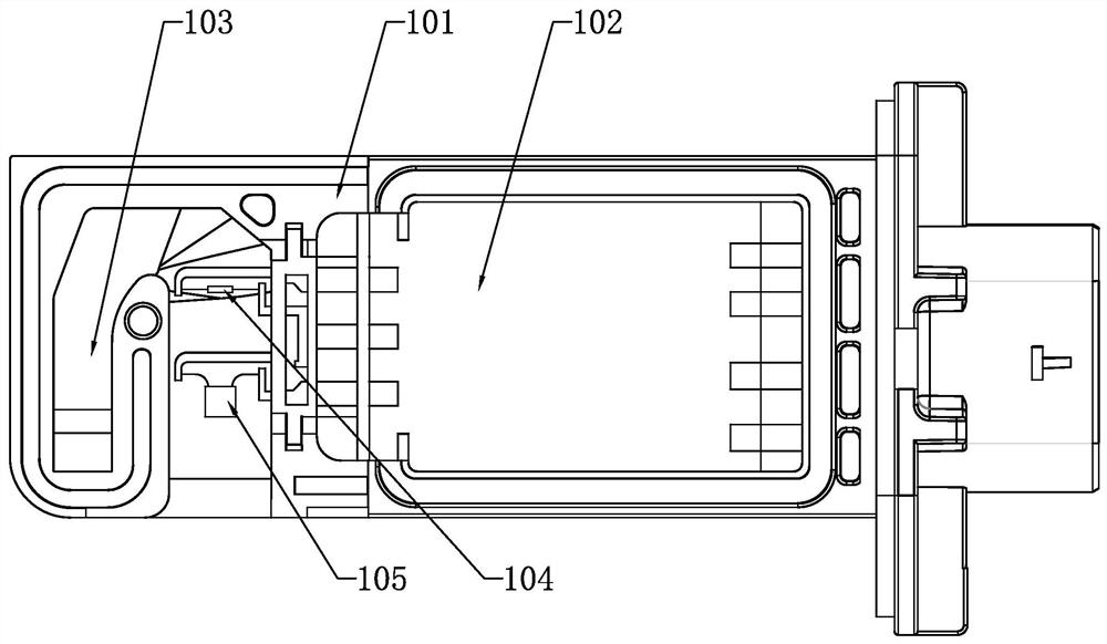
The invention discloses a weather-proof air flow sensor for monitoring air inlet temperature, and the sensor comprises a housing which is provided with a circuit board and an air measurement flow channel; the wind measuring element placing groove is communicated with the circuit board and the wind measuring flow channel; one end of the wind measuring element is connected with the circuit board, the other end of the wind measuring element penetrates through the wind measuring element placing groove and extends into the wind measuring flow channel, and the wind measuring element comprises a platinum wire resistor and a thermistor. In daily use, by adopting the technical scheme, when the air inlet temperature rises, the resistance value of the platinum wire resistor can also rise, and the resistance value of the thermistor can also be higher; the thermistor with a reasonable resistance value is added, so that the resistance value increase part of the thermistor and the platinum wire resistor caused by temperature rise can be equal, and according to the bridge balance principle, the same increment of the thermistor and the platinum wire resistor caused by temperature rise cannot influence the balance state of the bridge; therefore, the thermistor eliminates the influence of the air temperature on the flow measurement value.

Description

technical field [0001] The invention relates to an air flow sensor for weather-resistant intake air temperature monitoring and a process thereof. Background technique [0002] Air flow sensor, also known as air flow meter, is one of the important sensors of EFI engine. It converts the air flow inhaled into an electrical signal and sends it to the electronic control unit (ECU), as one of the basic signals for determining fuel injection. To monitor the mass flow of the engine intake air, in the current state of the art, the working environment does not consider whether the ambient temperature has an impact on the monitoring data. In this way, the detected data has a large error, and the components are affected by the air duct temperature, resulting in poor stability. The element circuit affects the thermal film element on the wind measuring element placement rack, which further causes the distortion of the detected air flow detection data. SUMMARY OF THE INVENTION [0003]...

Claims


Application Information

Patent Timeline
Patent Type & Authority Applications(China)
IPC IPC(8): G01F1/56G01K7/18G01K7/22G01K13/024
CPCG01F1/56G01K7/18G01K7/22G01K13/024
Inventor 朱邦海吴永斌吴进涛林敏
Owner 温州荣际新能源有限公司
Why Eureka
Try Eureka