


Quick Research
Generate reliable direction feasibility study reports for your R&D in just a few steps.

Technical Q&A
Discover and master advanced knowledge NOW. Basics, ideas, possibilities, all at once.

Find Solutions
As an expert in R&D theories, this can generate solutions to your technical problems instantly.

Evaluate Feasibility
Analyze your overall solution with one click, know your potential R&D risks in advance.

Monitor Landscape
Get weekly tech updates, stay abreast of the latest tech innovations and key insights.
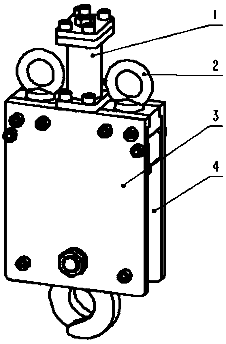
Load rejection device for underwater vehicle
A technology for underwater vehicles and rotating shafts, which can be applied to underwater ships, underwater operating equipment, transportation and packaging, etc. It can solve the problems of easy corrosion of electromagnet materials, easy rusting of steel balls, and many structural links, etc., to achieve Easy maintenance, less maintenance, and less driving force
- Summary
- Abstract
- Description
- Claims
- Application Information
AI Technical Summary
Problems solved by technology
Method used
Image

Examples
Embodiment
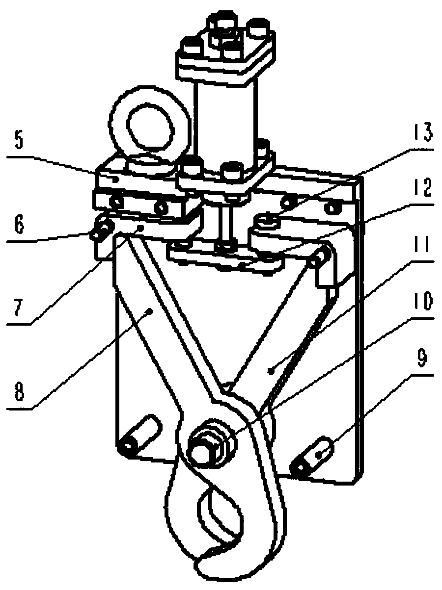
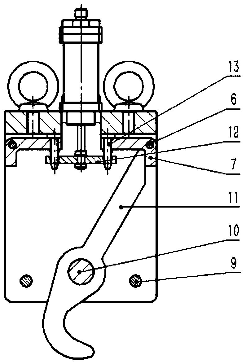
[0032] The action relationship of a load throwing device for underwater vehicles provided by the present invention is as follows: the ballast is hung in the round hole formed by the hooks of the left fork 8 and the right fork 11, and under the action of the gravity of the ballast, , the left fork 8 and the right fork 11 have a tendency to flare outwards. The straight rods of the left fork 8 and the right fork 11 are constrained by the limit block 7, and the limit block 7 is constrained by the tongue plate 12 through the pin shaft 13. The two ends of the tongue plate 12 are subjected to tension, the directions are opposite and the values are equal, achieving balance. When the hydraulic cylinder 1 moves, its piston rod drives the tongue plate 12 to move downward. When the tongue plate 12 cannot continue to constrain the pin shaft 13, the balance is broken. Under the gravity of the ballast, the left fork 8 and the right fork 11 are gradually opened to complete the dumping.
PUM
 Abstract
Description
Claims
Application Information
 - R&D Engineer
- R&D Manager
- IP Professional
- Industry Leading Data Capabilities
- Powerful AI technology
- Patent DNA Extraction
Browse by: Latest US Patents, China's latest patents, Technical Efficacy Thesaurus, Application Domain, Technology Topic, Popular Technical Reports.
© 2024 PatSnap. All rights reserved.Legal|Privacy policy|Modern Slavery Act Transparency Statement|Sitemap|About US| Contact US: help@patsnap.com