
Low-carbon additive supporting structure construction device, heading machine and construction method

A support structure and roadheader technology, which is applied in shaft equipment, earthwork drilling, shaft lining, etc., can solve problems such as synchronous support for tunnels, and achieve the effects of avoiding construction risks, ensuring structural quality, and fast construction speed

Pending Publication Date: 2022-07-29
CHINA RAILWAY ENGINEERING EQUIPMENT GROUP CO LTD
View PDF0 Cites 0 Cited by
  • Summary
  • Abstract
  • Description
  • Claims
  • Application Information

AI Technical Summary

Problems solved by technology

[0004] In view of the deficiencies in the above-mentioned background technology, the present invention proposes a low-carbon additive support structure application device, roadheader and construction method, which solves the problem that 3D printing used in tunnels cannot realize synchronous support in the prior art

Method used


Image

  • Low-carbon additive supporting structure construction device, heading machine and construction method
  • Low-carbon additive supporting structure construction device, heading machine and construction method
  • Low-carbon additive supporting structure construction device, heading machine and construction method

Examples


Embodiment 2

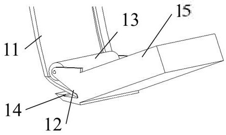
[0035] Example 2, which differs from Example 1 in that, as image 3 As shown, the fabric output mechanism 1 includes a fabric output housing 15, and the end of the fabric output housing 15 facing the rock wall 10 is provided with a fabric output port 12 for outputting the fabric 11 and a fabric rolling member for rolling the fabric 11 13. The other end of the fabric output housing 15 is fixed to the fabric output housing 15, and the fabric rolling element 13 rolls and adheres the fabric 11 output from the fabric output port 12 to the rock wall 10.

Embodiment 3

[0036] Example 3, the difference from Example 2 is that, as image 3 As shown, the end of the fabric output housing 15 close to the fabric output port 12 facing the rock wall 10 is provided with a nozzle 14 for spraying the adhesive, and the nozzle 14, the fabric output port 12 and the fabric rolling member 13 drive along the The rotation directions of the device 7 are set in sequence, so that after the nozzle 14 sprays the adhesive to the rock wall 10 , the fabric 11 is rolled on the rock wall 10 by the fabric rolling member 13 . Wherein, the fabric 11 is a flexible fabric. In this implementation, the binder is stored in the rear matching 9 , and the roadheader is provided with a pipeline and a pump for transporting the binder stored in the rear matching 9 to the spout 14 .

Embodiment 4

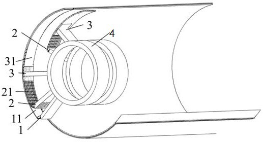
[0037] Example 4, the difference from Example 1 is that, as Figure 4 As shown, the reinforced material output mechanism 2 includes a reinforced material output casing 24, and one end of the reinforced material output casing 24 facing the rock wall 10 is provided with a reinforced material output port 22 for outputting the reinforced material 21 and a reinforced material output port 22 for rolling the reinforced material. 21, the other end of the reinforcement output housing 24 is fixed with the fabric output housing 15, and the reinforcement rolling piece 23 rolls the reinforcement 21 output from the reinforcement output port 22 to fit the fabric output. On the fabric 11 applied by the mechanism 1 . Wherein, the rib material 21 is a mesh-shaped or strip-shaped rib-shaped web. The pores of the rib material roll net allow the large particle components in the adhesive material 31 to pass through, ensuring that the adhesive material 31 does not segregate and evenly covers the ri...


PUM


Abstract

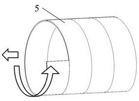
The invention discloses a low-carbon additive supporting structure construction device, a heading machine and a construction method. The low-carbon additive supporting structure construction device comprises a supporting structure construction device body arranged on the periphery of a driving device of the heading machine. And a fabric output mechanism, a rib material output mechanism and a rubber material output mechanism are sequentially arranged on the supporting structure construction device and are used for respectively constructing fabrics, rib materials and rubber materials to the rock wall, and the fabrics, the rib materials and the rubber materials form a composite supporting structure. The supporting structure construction device is arranged on the heading machine, excavation and lining of the supporting structure are synchronously carried out, the construction speed is high, the rigid supporting effect is timely, and the construction risk is avoided; the multi-layer overlapped spiral composite supporting structure is formed in a layered weaving and layer-by-layer bonding mode, the tensile property of rib materials and the compressive property of rubber materials are fully utilized, continuous construction can be achieved, the construction efficiency is improved, and the comprehensive cost is saved.

Description

technical field [0001] The invention relates to the technical field of tunnel support, in particular to a low-carbon additive support structure construction device, a roadheader and a construction method. Background technique [0002] The traditional tunnel support structure construction often adopts the shotcrete technique, in which special equipment is used for the bolting rod, vertical arch frame and shotcrete, and the cooperative work efficiency of each equipment is low. Poor working environment, etc. How to realize low-carbon, environmental protection and rapid construction of supporting structures has increasingly become the focus of the engineering community. [0003] Since the development of additive construction technology, it has been applied in many fields, and 3D printing buildings are gradually being known and accepted. However, this technology is rarely used in the field of tunnel construction. The main reasons are: (1) Rebar and concrete are difficult to sync...

Claims


Application Information

Patent Timeline
Patent Type & Authority Applications(China)
IPC IPC(8): E21D11/40E21D11/00
CPCE21D11/406E21D11/003
Inventor 李洋白中坤毕程程朱毅王宁李应飞王亚威
Owner CHINA RAILWAY ENGINEERING EQUIPMENT GROUP CO LTD
Learn More