Quantity-controllable anti-blocking device for plastic particle discharging
An anti-blocking and particle-preventing technology, which is applied in the direction of conveyor control devices, transportation and packaging, loading/unloading, etc., can solve the problems that plastic particles are easy to block the feeding channel and plastic particles are easy to stick, so as to prevent blockage and prevent The effect of sticky lumps of raw materials
- Summary
- Abstract
- Description
- Claims
- Application Information
AI Technical Summary
Problems solved by technology
Method used
Image

Examples
Embodiment 1
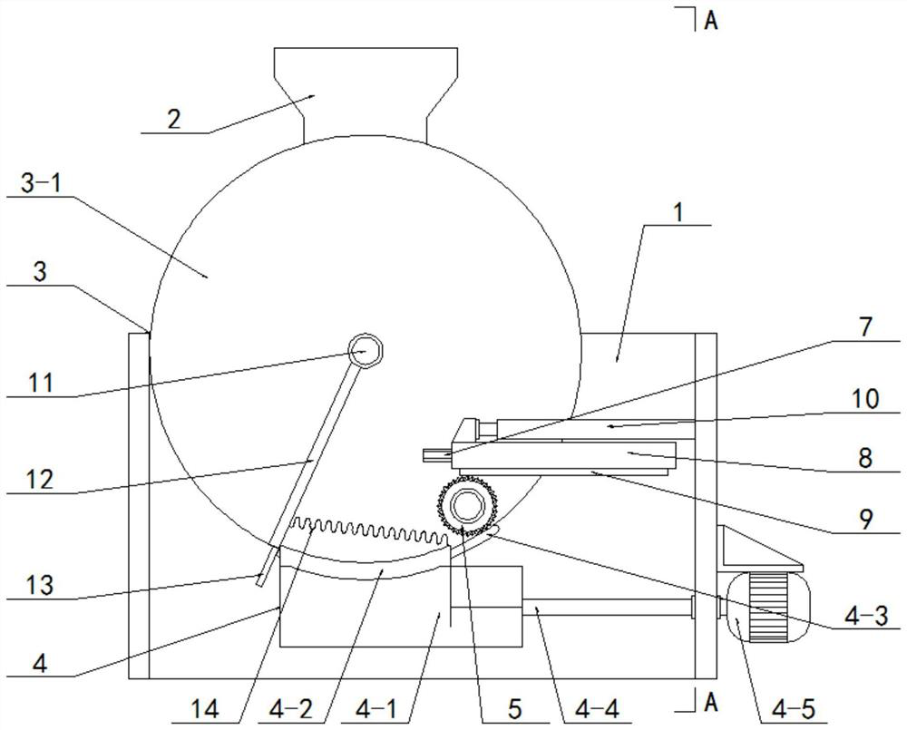
[0041] like figure 1 , 2 As shown, this embodiment includes a bracket 1, an upper hopper 2, wherein the upper hopper 2 is fixedly arranged on the bracket 1, and it also includes:
[0042] The stirring device 3, the stirring device 3 is arranged on the support 1, and the outlet end of the upper hopper 2 is arranged through the inlet end of the stirring device 3;
[0043] The feeding device 4, the feeding device 4 is arranged on the support 1, and the outlet end of the stirring device 3 is arranged through the inlet end of the feeding device 4;
[0044] With the above design scheme, when discharging the material ions, the raw materials are sent into the stirring device 3 through the upper hopper 2 for storage, and when the material is discharged, the material stored in the stirring device 3 is stored in the discharging device 4 through the unloading device 4. Raw materials sent.
Embodiment 2
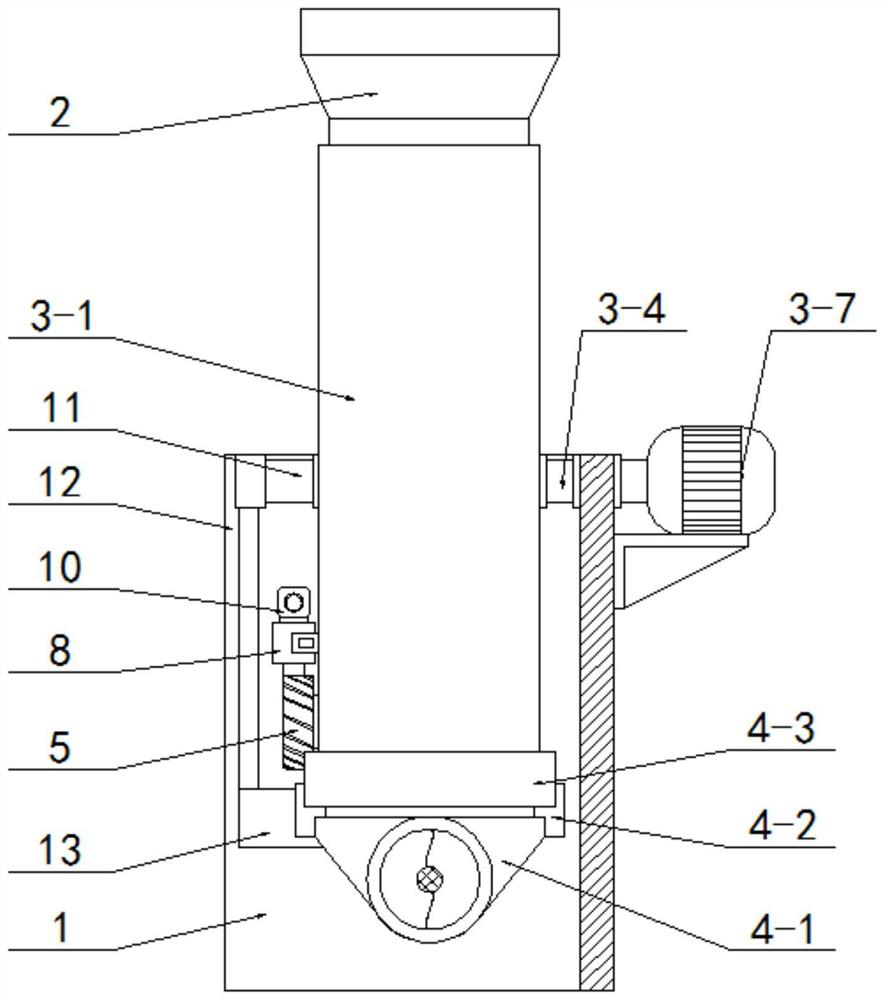
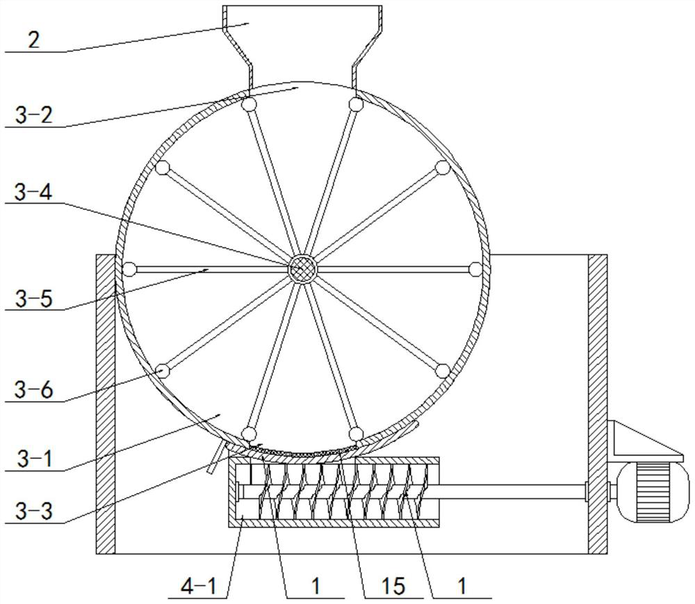
[0046] like image 3 As shown, on the basis of the above-mentioned embodiment 1, the stirring device 3 includes:
[0047] The drum 3-1, the drum 3-1 is fixed on the bracket 1 by screws, the upper side wall of the drum 3-1 is provided with a feeding port 3-2, and the lower end of the upper hopper 2 is inserted and fixed at the feeding port within 3-2;
[0048] A drive shaft 3-4, the drive shaft 3-4 is screwed on the bracket 1 through a bearing, and the front end of the drive shaft 3-4 is passed through and screwed on the rear side plate of the drum 3-1 through a bearing;
[0049] Connecting frames 3-5, the connecting frames 3-5 are several, and are fixed on the drive shaft 3-4 by screws at equal angles in the drum 3-1;
[0050] The pick 3-6, the pick 3-6 is fixed on the end of the connecting frame 3-5 away from the drive shaft 3-4 by screws, and the pick 3-6 is movable against the inner side wall of the drum 3-1 superior;
[0051] The stirring motor 3-7, the stirring motor ...
Embodiment 3
[0054] like figure 2 , 3 , 4, on the basis of the above-mentioned embodiment 2, the described blanking device 4 comprises:
[0055] The transfer bucket 4-1, the transfer bucket 4-1 is fixed on the bracket 1 by screws, the lower side wall of the drum 3-1 is provided with a discharge port 3-3, and the drum 3-1 passes through the discharge port 3- 3 Connect with the transfer bucket 4-1;
[0056] There are two arc-shaped grooves 4-2, and the two arc-shaped grooves 4-2 are symmetrically arranged on the front and rear sides of the discharge port 3-3;
[0057] The sealing plate 4-3, the sealing plate 4-3 is covered and arranged under the discharge port 3-3, and the front and rear sides of the sealing plate 4-3 are respectively slidably arranged on the arc grooves 4-3 on the front and rear sides. 2;
[0058] The spiral feeding roller 4-4, the spiral feeding roller 4-4 is arranged in the transfer hopper 4-1, and the left end shaft of the spiral feeding roller 4-4 is screwed throug...
PUM
 Abstract
Description
Claims
Application Information
 - R&D
- Intellectual Property
- Life Sciences
- Materials
- Tech Scout
- Unparalleled Data Quality
- Higher Quality Content
- 60% Fewer Hallucinations
Browse by: Latest US Patents, China's latest patents, Technical Efficacy Thesaurus, Application Domain, Technology Topic, Popular Technical Reports.
© 2025 PatSnap. All rights reserved.Legal|Privacy policy|Modern Slavery Act Transparency Statement|Sitemap|About US| Contact US: help@patsnap.com