Extrusion forming equipment for processing nano sponge composite acoustic panel and production process

A nano-sponge and extrusion molding technology, which is applied in the field of processing equipment for nano-sponge composite sound-absorbing panels, can solve troubles and other problems

Pending Publication Date: 2022-07-29
安冬莹
View PDF23 Cites 0 Cited by
  • Summary
  • Abstract
  • Description
  • Claims
  • Application Information

AI Technical Summary

Problems solved by technology

[0003] The existing nano-sponge sound-absorbing panel extrusion molding machine usually pours the sound-absorbing panel blank into the mold above the molding machine, and then squeezes the blank in the mold through a pressing plate to produce it. The inner walls fit together, so that when people take the sound-absorbing panel out of the mold by hand, they need to dig out the sound-absorbing panel from the mold by hand, which makes it too troublesome to take the sound-absorbing panel out of the mold

Method used


Image

  • Extrusion forming equipment for processing nano sponge composite acoustic panel and production process
  • Extrusion forming equipment for processing nano sponge composite acoustic panel and production process
  • Extrusion forming equipment for processing nano sponge composite acoustic panel and production process

Examples


Embodiment 1

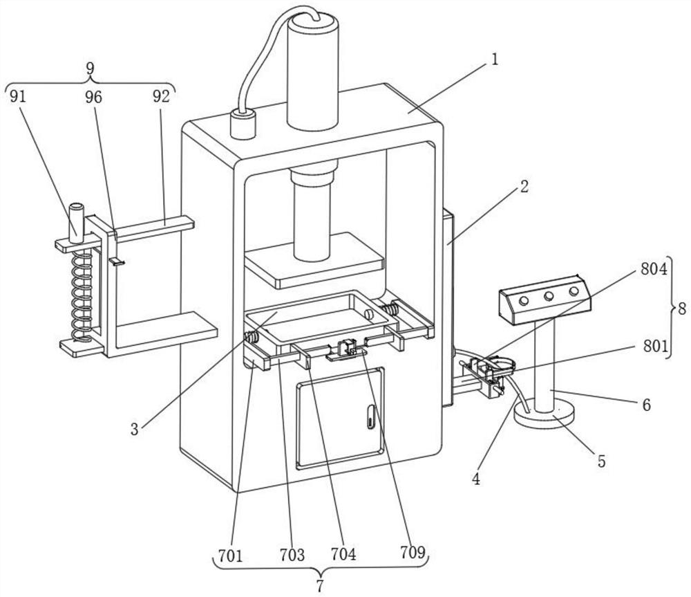
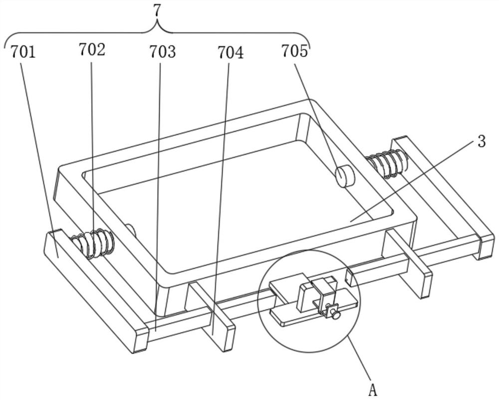
[0031] Example 1, as Figure 1-8 As shown, the present invention provides an extrusion molding equipment for processing nano-sponge composite sound-absorbing panels, including a main body 1 and a pushing device 7, the main body 1 is an extrusion molding machine, and a connecting block 2 is fixedly connected to one side of the main body 1.

[0032] The specific settings and functions of the pushing device 7 , the fixing device 8 and the storage device 9 will be described in detail below.

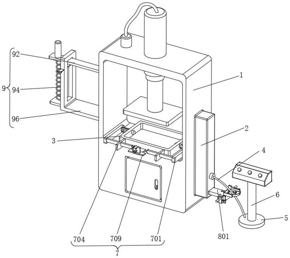
[0033] like image 3 and Figure 4 As shown, the side of the connection block 2 away from the main body 1 is provided with a wire 4, the end of the wire 4 away from the connection block 2 is provided with a tray 5, one end of the tray 5 is fixedly connected with a support column 6, and the inner wall of the main body 1 is fixedly connected with a mold 3 , first pour the sound-absorbing plate blank into the mold 3, and then extrude the sound-absorbing plate through the body 1, and then turn ...

Embodiment 2

[0037] Embodiment 2, on the basis of Embodiment 1, the side of the main body 1 away from the connection block 2 is provided with a storage device 9, the storage device 9 includes a placement plate 95, one end of the placement plate 95 is fixedly connected to the body 1, and the placement plate 95 In the shape of "L", first place the processed sound-absorbing panel on the placing plate 95, and then pull the limit block 93 to make the limit block 93 slide inside the placing plate 95, so that the limit block 93 is not in phase with the sliding plate 92. contact, so that the third spring 94 pulls the sliding plate 92 due to the recovery of the elastic force, so that the sliding plate 92 slides on the inner wall of the chute 96. At this time, the sliding plate 92 will be in contact with the sound-absorbing plate, so that the sound-absorbing plate is fixed by the pressure of the sliding plate 92 On the placing plate 95, a limit block 93 is inserted through one side of the placing pla...


PUM


Abstract

The invention provides extrusion forming equipment for nano sponge composite acoustic panel processing and a production process, and relates to the technical field of nano sponge composite acoustic panel processing equipment.The extrusion forming equipment comprises a body and a pushing device.The body is an extrusion forming machine, a connecting block is fixedly connected to one side of the body, and a wire is arranged on the side, away from the body, of the connecting block; a tray is arranged at the end, away from the connecting block, of the wire, a supporting column is fixedly connected to one end of the tray, a mold is fixedly connected to the inner wall of the body, pushing devices are arranged on the two sides of the mold, each pushing device comprises two cylinders, and the two cylinders are inserted into the two sides of the mold in a penetrating mode. The device solves the problem that the sound-absorbing plate needs to be dug out of the mold by hands when being taken out of the mold by hands due to the fact that the sound-absorbing plate is attached to the inner wall of the mold after being extruded and formed, and the sound-absorbing plate is too troublesome to be taken out of the mold.

Description

technical field [0001] The invention relates to the technical field of processing equipment for nano-sponge composite sound-absorbing panels, in particular to extrusion molding equipment and a production process for processing nano-sponge composite sound-absorbing panels. Background technique [0002] The extrusion molding machine is mainly divided into: extruder and rolling machine. Generally, the processing method of blank is adopted. The processing process is that the blank is extruded from the orifice or gap of the die to make it horizontal under the action of three-way uneven compressive stress. The cross-sectional area is reduced, the length is increased, and it becomes the desired product, especially cold extrusion. The material utilization rate is high, the structure and mechanical properties of the material are improved, the operation is simple, and the productivity is high. Sectional parts are important less without cutting process. [0003] The existing nano-spon...

Claims


Application Information

Patent Timeline
Patent Type & Authority Applications(China)
IPC IPC(8): B29C43/02B29C43/32B29C43/50B29C37/00B29L7/00
CPCB29C43/02B29C43/32B29C43/50B29C37/00B29C2037/94B29L2007/002
Inventor 安冬莹刘维龙
Owner 安冬莹
Why Eureka
Try Eureka