
New energy automobile exhaust pipe inner wall burr cleaning device

A new energy vehicle and cleaning device technology, applied in the field of new energy vehicle exhaust pipe inner wall burr cleaning device, can solve the problems of low work efficiency and achieve high work efficiency

Pending Publication Date: 2022-07-29
张彩丽
View PDF1 Cites 1 Cited by
  • Summary
  • Abstract
  • Description
  • Claims
  • Application Information

AI Technical Summary

Problems solved by technology

[0005] In order to overcome the above-mentioned patent, although the burrs on the inner wall of the exhaust pipe can be removed, the burrs on the inner wall of one exhaust pipe can only be removed at a time, and the work efficiency is low. The burrs on the inner wall of the new energy vehicle exhaust pipe are cleaned with high work efficiency.

Method used


Image

  • New energy automobile exhaust pipe inner wall burr cleaning device
  • New energy automobile exhaust pipe inner wall burr cleaning device
  • New energy automobile exhaust pipe inner wall burr cleaning device

Examples


Embodiment 1

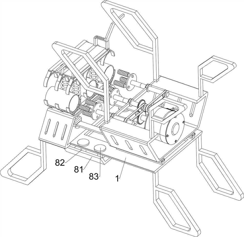
[0033] A burr cleaning device for the inner wall of an exhaust pipe of a new energy vehicle, comprising a support frame 1, a grinding roller 2, a mounting frame 3, a drive mechanism 4 and a limit mechanism 5, please refer to Figure 1-Figure 6 As shown in the figure, the mounting bracket 3 is installed on the left side of the outer top of the support frame 1 by welding, and the positioning blocks are fixed on the right part of the upper three sides of the upper part of the mounting frame 3. The operator can place the exhaust pipe on the mounting frame 3 , a drive mechanism 4 is installed on the support frame 1, the drive mechanism 4 is used to provide power, and three groups of grinding rollers 2 are installed on the driving mechanism 4, and the number of each group of grinding rollers 2 is three. When the grinding rollers 2 rotate, the grinding rollers 2. The burrs on the inner wall of the exhaust pipe can be removed. A limit mechanism 5 is installed on the left of the support...

Embodiment 2

[0040] On the basis of Embodiment 1, a cleaning mechanism 6 is also included. The cleaning mechanism 6 includes a fixing rod 61 , a magnet block 62 , a fixing frame 63 , a rotating shaft 64 , a scroll spring 65 , a limiting cylinder 66 , and a guide post 67 , second spring 68, magnet 69 and cleaning disc 610, see figure 1 and Figure 7 As shown, three fixing frames 63 are installed on the upper part of the left side of the support frame 1 evenly spaced by welding, and a rotating shaft 64 is rotatably connected between the upper parts of the three fixing frames 63. The front and rear sides of the rotating shaft 64 are respectively A scroll spring 65 is connected with the upper part of the outer side of the fixing frame 63 on the front and rear sides. The fixed sleeve on the rotating shaft 64 is evenly spaced with three limiting cylinders 66. There is a guide post 67, a second spring 68 is wound between the left end of the guide post 67 and the outer left side of the limiting c...

Embodiment 3

[0045] On the basis of Embodiment 1 and Embodiment 2, a collection mechanism 8 is also included. The collection mechanism 8 includes a collection frame 81, a mounting rod 82 and a fixed threaded disk 83. Please refer to figure 1 and Figure 10 As shown in the figure, two mounting rods 82 are slidably connected with two mounting rods 82 on the bottom left side of the bottom of the support frame 1. The top of the mounting rods 82 is connected with a fixed threaded disk 83 through a threaded rotating type, and the bottom ends of the four mounting rods 82 pass through A collection frame 81 is installed in a welded connection. When the chips are pushed out, the collection frame 81 can collect the chips.

[0046] Also includes a material guide mechanism 9, the material guide mechanism 9 includes a fixed column 91 and a guide plate 92, please refer to figure 1 and Figure 11 As shown, the bottom left side of the bottom of the fixing frame 63 is symmetrically fixed with a fixed colu...


PUM


Abstract

The invention relates to a burr cleaning device, in particular to a new energy automobile exhaust pipe inner wall burr cleaning device. The new energy automobile exhaust pipe inner wall burr removing device which can remove burrs on the inner walls of three exhaust pipes at the same time and is high in working efficiency needs to be designed. A new energy automobile exhaust pipe inner wall burr cleaning device comprises a supporting frame, a mounting frame, a driving mechanism and the like, the mounting frame used for placing an exhaust pipe is fixedly connected to the left side of the outer top of the supporting frame, and the driving mechanism used for providing power is installed on the supporting frame. Three exhaust pipes are placed on the mounting frame, the driving mechanism is started to drive the grinding roller to rotate, then the driving mechanism is pulled to move leftwards to drive the grinding roller to move leftwards, meanwhile, the driving mechanism further drives the limiting mechanism to operate to press and fix the exhaust pipes, the grinding roller moves leftwards, and then burrs on the inner walls of the exhaust pipes are removed. And burrs on the inner walls of three exhaust pipes can be removed at the same time, and the working efficiency is high.

Description

technical field [0001] The invention relates to a burr cleaning device, in particular to a burr cleaning device for the inner wall of an exhaust pipe of a new energy vehicle. Background technique [0002] When the exhaust pipe is produced, there will be a lot of burrs on the inner wall of the exhaust pipe. In order to ensure the exhaust effect of the exhaust pipe, it is generally necessary to remove the burrs on the inner wall of the exhaust pipe. [0003] The Chinese patent with publication number CN113829147A discloses an inner wall grinding device for the production of exhaust pipes of new energy vehicles, including a base, a support plate is fixedly connected to the top left outer wall of the base, and the interior of the support plate is hollowed out. A support rod is fixedly connected to the top central axis of the base, and an arc clip is fixedly connected to one end of the support rod away from the base. The inner wall grinding device for the production of exhaust p...

Claims


Application Information

Patent Timeline
Patent Type & Authority Applications(China)
IPC IPC(8): B24B9/00B24B5/40B24B27/00B24B41/00B24B47/12B24B41/06B24B55/06
CPCB24B9/00B24B5/40B24B27/0061B24B41/00B24B47/12B24B41/061B24B55/06
Inventor 张彩丽
Owner 张彩丽
Learn More