
Automatic spraying equipment

A technology of automatic spraying and equipment, which is applied in the direction of spraying booths, spraying devices, and cleaning methods using liquids, etc. It can solve the problems of lower paint rate than others, troublesome equipment cleaning, and waste of paint, so as to achieve uniform paint film thickness and reduce Long spraying time and cost-saving effect

Pending Publication Date: 2022-07-29
孙溦
View PDF0 Cites 0 Cited by
  • Summary
  • Abstract
  • Description
  • Claims
  • Application Information

AI Technical Summary

Problems solved by technology

[0003] In the prior art, when reciprocating automatic spraying equipment is used, the imitation program of the reciprocating spraying machine can only be adjusted by telescopic adjustment, and the angle cannot be adjusted, so the reciprocating spraying machine cannot completely achieve vertical spraying, so the paint rate on the side surface of the workpiece is low In other positions, the paint film on the side surface of the workpiece is relatively thin, and the extension of the plane profiling program or the change of the gun closing time can make the plane reciprocating machine spray to this area, but it causes a waste of paint and increases the cost of spraying work At the same time, if the side spraying is carried out by fixing the nozzle on the side, it is necessary to increase the pipeline. When the equipment is not in use, the pipeline needs to be cleaned to prevent the residual paint in the pipeline from solidifying and blocking the pipeline and nozzle. Cleaning and maintenance It is necessary to remove the nozzles on the top and both sides for cleaning, which will cause troublesome equipment cleaning.

Method used


Image

  • Automatic spraying equipment
  • Automatic spraying equipment
  • Automatic spraying equipment

Examples


Embodiment approach

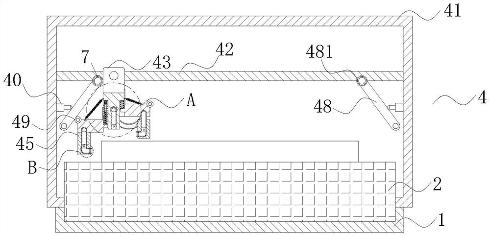
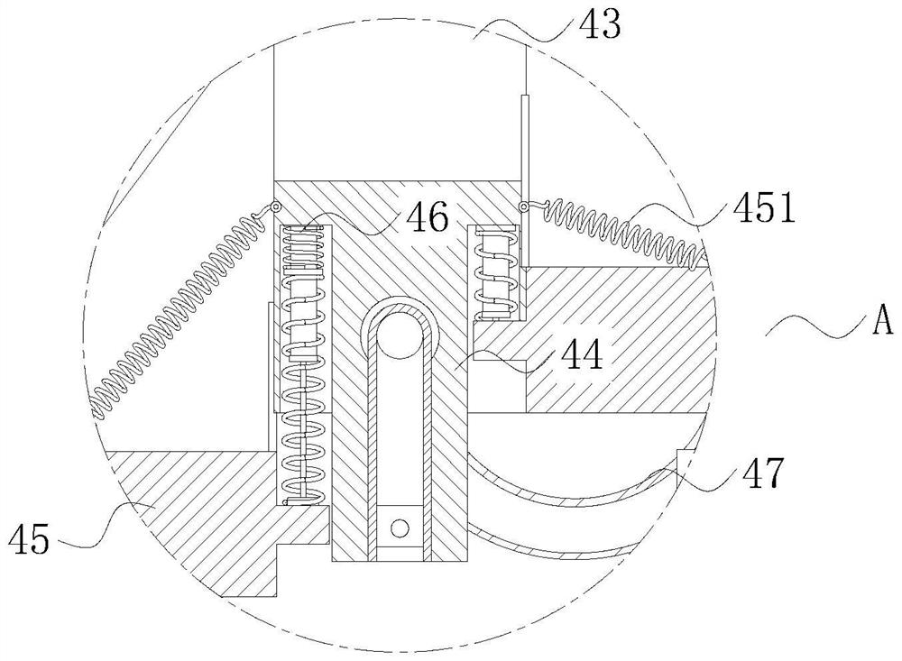
[0038] As an embodiment of the present invention, such as figure 1 , figure 2 , image 3 As shown, the spraying mechanism 4 includes a first housing 41, a rail 42, a moving assembly 43, a first spray gun 44, a second spray gun 45, a second spring 451, a first spring 46, a spray pipe 47, a limit plate 48 and roller 49;

[0039] A first housing 41 is fixedly connected to the upper end of the base 1 near the control assembly 3, a rail 42 is fixedly connected to an inner surface of the first housing 41, and a moving component 43 is slidably connected to the outer surface of the rail 42. A first spray gun 44 is fixedly connected to the lower end of the moving assembly 43 , a second spray gun 45 is symmetrically slidably connected to the outer surface of the lower end of the first spray gun 44 , and a first spring 46 is fixedly connected to one end of the second spray gun 45 . The upper end of 46 is fixedly connected to the first spray gun 44, the outer surface of the second spr...


PUM


Abstract

The invention relates to the technical field of automatic spraying, in particular to automatic spraying equipment which comprises a base, and a transmission assembly is fixedly connected to the upper end of the base; a control assembly; an exhaust pipe; a spraying mechanism is fixedly connected to the position, close to the control assembly, of the upper end of the base, and the spraying mechanism can evenly spray paint to the side surface of the workpiece in the spraying process. By arranging the spraying mechanism, when the first spraying gun completes transverse displacement and advances to a terminal, a second spraying gun sprays the side surface of a workpiece through limitation of a limiting plate, the second spraying gun is positioned to the side surface of the workpiece in a rolling friction mode, and the workpiece does not make contact with the second spraying gun in the advancing process; the effect of uniformly spraying the side surface of the workpiece is achieved, the effect that the thickness of paint films on all the surfaces of the workpiece is uniform is achieved, meanwhile, the spraying duration of the first spraying gun is shortened, waste of paint is avoided, and the production cost is saved.

Description

technical field [0001] The invention relates to the technical field of automatic spraying, in particular to an automatic spraying device. Background technique [0002] Automatic spraying equipment is a special tool that automatically covers metal and non-metal surfaces with a protective layer or decorative layer, and replaces manual labor with intelligence. Generally use reciprocating automatic spraying equipment; [0003] When using the reciprocating automatic spraying equipment in the prior art, the replica program of the reciprocating spraying machine can only be adjusted by telescopic adjustment, but cannot be adjusted in angle, so the reciprocating spraying machine cannot completely achieve vertical spraying, so the paint rate on the side surface of the workpiece is low. In other positions, the paint film on the side surface of the workpiece is relatively thin, and prolonging the plane profiling program or changing the gun closing time, although the plane reciprocator ...

Claims


Application Information

Patent Timeline
Patent Type & Authority Applications(China)
IPC IPC(8): B05B16/00B05B13/04B05B12/00B05B14/40B05B15/68B08B1/00B08B1/04B08B3/02
CPCB05B16/90B05B13/041B05B12/00B05B15/68B05B14/40B08B3/02B08B1/165B08B1/32
Inventor 孙溦郑家龙
Owner 孙溦
Learn More