Ore dressing machine and intelligent ore dressing method
A technology of mineral processing machine and mineral processing tank, which is applied in the direction of chemical instruments and methods, wet separation, solid separation, etc., can solve the problems of low mineral processing precision and hinder the development and utilization of mineral resources, and achieve high mineral processing efficiency, simple structure and stable operation good sex effect
- Summary
- Abstract
- Description
- Claims
- Application Information
AI Technical Summary
Problems solved by technology
Method used
Image

Examples
specific Embodiment 2
[0061] This embodiment also provides a concentrator whose structure is basically the same as that of Embodiment 1, and the differences are:
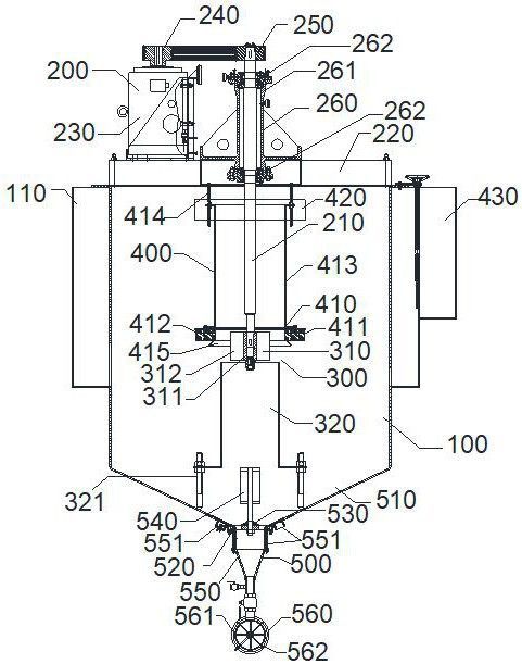
[0062] like Figure 5 and Image 6 As shown, the vertical section of the blade 312 is composed of at least two different types of polygonal pieces; one edge of one polygonal piece is in contact with the outer wall of the hub 311, and along the vertical direction, the The width is equal from top to bottom or narrow at the top and wide at the bottom. The cross section of the blade 312 may be composed of right-angled trapezoids and rectangles, or may be composed of triangles and right-angled trapezoids, or may be composed of triangles and rectangles, which are not specifically limited herein. The buffer member 411 is composed of an annular structure formed by connecting at least one buffer plate end to end.
specific Embodiment 3
[0063] This embodiment also provides a concentrator whose structure is basically the same as that of Embodiment 1, and the differences are:
[0064] like Figure 5 to Figure 7 As shown, the vertical section of the blade 312 is composed of at least two polygonal pieces with different areas. One edge of one of the polygonal pieces is in contact with the outer wall of the hub 311 , and along the vertical direction, the widths of the blades are equal from top to bottom or are narrow at the top and wide at the bottom. The cross section of the blade 312 may be composed of two or more squares with different areas, may also be composed of two or more rectangles with different areas, or may be composed of two or more rectangles with different areas. is composed of right-angled trapezoids, which are not specifically limited here.
[0065] Further, the adjusting member 414 includes at least one adjusting hole provided on the isolation pipe 413, a screw rod matched with the adjusting ho...
specific Embodiment 4
[0066] This embodiment also provides a concentrator whose structure is basically the same as that of Embodiment 1, and the differences are:
[0067] The blades 312 are helical along the outer wall of the hub 311 , and the widths of the blades remain the same from top to bottom, or the widths of the blades gradually increase from top to bottom, and the helical blades 312 can also be used. The purpose of driving the rotation of the pulp is achieved, so that high-density minerals can be quickly enriched at the bottom of the beneficiation tank 100 .
[0068] Further, as Figure 4 As shown, the top of the blade 312 is provided with a top sheet 313 in order to prevent high-density minerals from floating up, conduct the energy of the pulp outside the impeller downward, and drain the high-density minerals to the bottom of the beneficiation tank 100 .
[0069] Further, the inner diameter of the first deflector 415 is gradually increased from top to bottom along the vertical direction,...
PUM
 Abstract
Description
Claims
Application Information
 - R&D
- Intellectual Property
- Life Sciences
- Materials
- Tech Scout
- Unparalleled Data Quality
- Higher Quality Content
- 60% Fewer Hallucinations
Browse by: Latest US Patents, China's latest patents, Technical Efficacy Thesaurus, Application Domain, Technology Topic, Popular Technical Reports.
© 2025 PatSnap. All rights reserved.Legal|Privacy policy|Modern Slavery Act Transparency Statement|Sitemap|About US| Contact US: help@patsnap.com