
Controller of vacuum pump

Inactive Publication Date: 2005-02-10
KAWAGUCHI MASAHIRO +4
View PDF3 Cites 23 Cited by
  • Summary
  • Abstract
  • Description
  • Claims
  • Application Information

AI Technical Summary

Benefits of technology

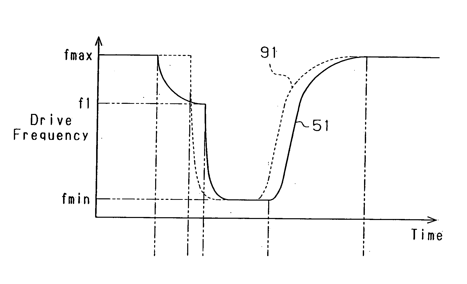
[0016] The controller of the present invention performs deceleration control to decrease the rotational speed of the electric motor section when an increase in load torque of the vacuum pump per unit time abruptly changes upward. This reduces shocks applied to the components of the vacuum pump by the abrupt upward change in the increase in load torque of the vacuum pump per unit time or the continuous state where the increase in load torque of the vacuum pump per unit time is large after the upward change of the load torque when the load torque rises. It is therefore unnecessary to reinforce the components of the vacuum pump in order to improve the shock resistance, thereby preventing a reinforcement-originated size increase or weight increase of the vacuum pump.

Problems solved by technology

When an electric motor is used as the drive source for the vacuum pump, the abrupt increase in pressure load quickly increases the output torque of the electric motor or the load torque of the vacuum pump.
That is, the load torque of the vacuum pump rapidly increases.
Although the aforementioned control mode prevents the components of the vacuum pump from being damaged by an excess increase in load torque of the vacuum pump, a rapid rise in load torque occurs when the closed state of the valve is switched to the open state.
Even if the control mode prevents an excess increase in load torque of the vacuum pump, therefore, the components of the vacuum pump may be shocked significantly by an abrupt upward change in the increased speed of the load torque or continuation of the state at which the increased speed is great after the upward change.
This causes the components of the vacuum pump to be damaged.
This however, undesirably leads to enlargement and weight increase of the vacuum pump.

Method used


Image

  • Controller of vacuum pump
  • Controller of vacuum pump
  • Controller of vacuum pump

Examples


Embodiment Construction

[0021] One embodiment of the invention as embodied in a vacuum pump for evacuating a load-lock chamber in a semiconductor production apparatus is described below with reference to the accompanying drawings.

[0022] As shown in FIG. 1, a process chamber 12 is provided side-by-side with respect to a load-lock chamber 13 in a semiconductor production apparatus 11. Deposition processes, such as vacuum deposition or sputtering on a wafer, are carried out in the process chamber 12. Those processes are executed after the process chamber 12 is set to a predetermined degree of vacuum by using an unillustrated evacuation system.

[0023] Wafer exchange between the exterior (atmospheric pressure space) of the semiconductor production apparatus 11 and the process chamber 12 is carried out via the load-lock chamber 13. That is, a passage for exchanging a wafer at the time of wafer exchange is provided between both chambers 12 and 13 and a gate valve 14 that connects and disconnects both chambers 12...


PUM


Abstract

A vacuum pump has a pump mechanism section that performs evacuation to set a space to be evacuated to a predetermined degree of vacuum and an electric motor section for driving the pump mechanism section. A controller of the vacuum pump executes deceleration control to decrease a rotational speed of the electric motor section when an increase in load torque of the vacuum pump per unit time abruptly changes upward.

Description

BACKGROUND OF THE INVENTION [0001] The present invention relates to a controller of a vacuum pump having a pump mechanism section that performs evacuation to set a space to be evacuated to a predetermined degree of vacuum, and an electric motor section for driving the pump mechanism section. [0002] There is known a semiconductor production apparatus of a type that has a load-lock chamber provided side-by-side with respect to a process chamber that performs film deposition and other processes to a wafer (substrate) as described in, for example, Japanese Patent Laid-Open Publication No. 9-306972. [0003] This apparatus performs wafer exchange between the process chamber and the semiconductor production apparatus exterior via the load-lock chamber. A vacuum pump that sets the load-lock chamber to a predetermined degree of vacuum is connected via a valve to the load-lock chamber. This valve is designed in such a way as to be able to connect or disconnect the load-lock chamber to or from ...

Claims


Application Information

Patent Timeline
IPC IPC(8): H01L21/00F04B37/16F04B49/06
CPCF04B49/06H01L21/67017
Inventor KAWAGUCHI, MASAHIROYAMAMOTO, SHINYASATO, DAISUKEKOSHIZAKA, RYOSUKEKURAMOTO, SATORU
Owner KAWAGUCHI MASAHIRO
Learn More