
Hydrodynamic cavitation assisted liquid-liquid extraction device and extraction method

A technology of hydrodynamic cavitation and extraction device, applied in chemical instruments and methods, liquid solution solvent extraction, mixing methods, etc., can solve the problems of low extraction efficiency, fast layering speed, unfriendly environment, etc. The effect of enhancing the degree of mixing

Pending Publication Date: 2022-07-29
LIAONING UNIVERSITY
View PDF12 Cites 0 Cited by
  • Summary
  • Abstract
  • Description
  • Claims
  • Application Information

AI Technical Summary

Problems solved by technology

Liquid-liquid extraction generally adopts the method of mixing, stirring, standing and stratifying, and the extraction equipment such as separatory funnel, extraction column, extraction tank, etc. all need to be stirred, especially in the extraction process of the water phase and the oil phase, the existing The way of adding raw materials and extractant is to directly input the extraction equipment. Due to the rapid delamination of the extractant and raw materials, it is difficult to mix the extractant and raw materials directly into the extraction equipment, resulting in low extraction efficiency.
In addition, the general liquid-liquid extraction process has disadvantages such as time-consuming operation, large consumption of organic solvents, unfriendly to the environment, difficulty in extracting highly water-soluble components from water, and prone to emulsification.

Method used


Image

  • Hydrodynamic cavitation assisted liquid-liquid extraction device and extraction method
  • Hydrodynamic cavitation assisted liquid-liquid extraction device and extraction method
  • Hydrodynamic cavitation assisted liquid-liquid extraction device and extraction method

Examples


Embodiment 1

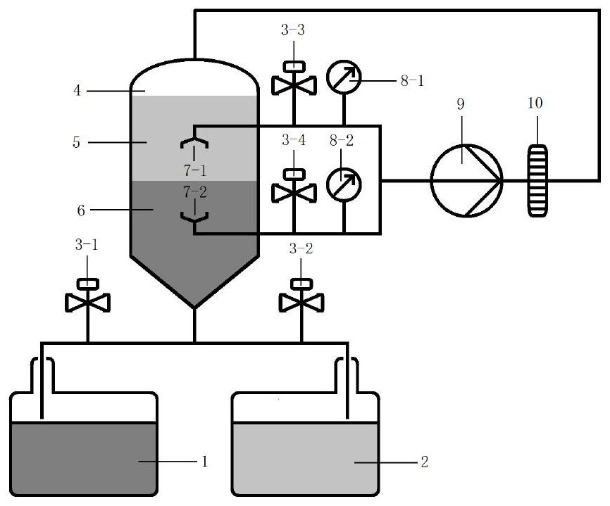
[0025] Example 1 Orifice plate type hydraulic cavitation-assisted liquid-liquid extraction device

[0026] like figure 1 As shown, the orifice plate type hydraulic cavitation assisted liquid-liquid extraction device includes: horizontal storage tank I (1), horizontal storage tank II (2), extraction tank (4), pressure pump (9) and hydraulic Cavitation device.

[0027] In this embodiment, the orifice plate (10) is selected for the hydraulic cavitation device. The orifice plate (10) is a cylindrical plate with 1-100 through holes. The through holes are cylindrical holes or square holes. Preferably, in this embodiment, the orifice plate (10) is a cylindrical plate with a thickness of 4 mm, and the orifice plate is provided with three through holes, and the through holes are cylindrical holes with a diameter of 5 mm.

[0028] A valve I (3-1) is connected to the inlet pipe of the horizontal storage tank I (1).

[0029] A valve II (3-2) is connected to the inlet pipe of the hori...

Embodiment 2

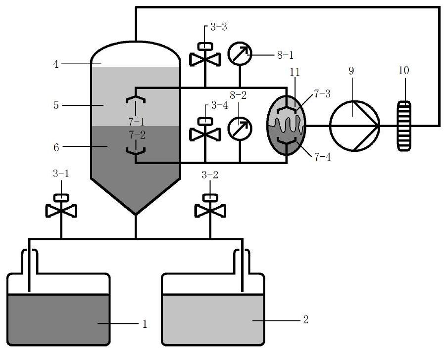
[0036] Example 2 Liquid-liquid extraction device assisted by collider and orifice plate type hydraulic cavitation

[0037] like figure 2 As shown in the figure, the collider and orifice type hydraulic cavitation-assisted liquid-liquid extraction device includes: horizontal storage tank I (1), horizontal storage tank II (2), extraction tank (4), pressure pump ( 9), a collider (11) and a hydraulic cavitation device.

[0038] In this embodiment, the orifice plate (10) is selected for the hydraulic cavitation device. The orifice plate (10) is a cylindrical plate with 1-100 through holes. The through holes are cylindrical holes or square holes. Preferably, in this embodiment, the orifice plate (10) is a cylindrical plate with a thickness of 4 mm, and the orifice plate is provided with three through holes, and the through holes are cylindrical holes with a diameter of 5 mm.

[0039] A valve I (3-1) is connected to the inlet pipe of the horizontal storage tank I (1).

[0040] A...

Embodiment 3

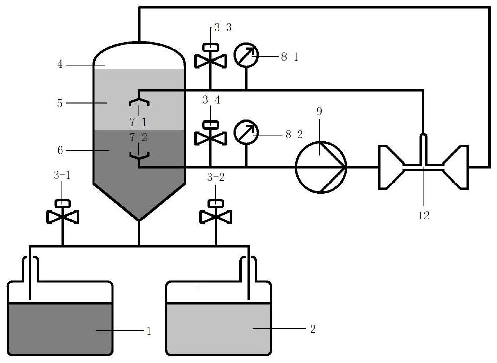
[0047] Example 3 Venturi-type hydraulic cavitation-assisted liquid-liquid extraction device

[0048] like image 3 As shown in the figure, the Venturi-type hydraulic cavitation-assisted liquid-liquid extraction device includes: horizontal storage tank I (1), horizontal storage tank II (2), extraction tank (4), pressure pump (9) and Hydraulic cavitation device.

[0049] In this embodiment, the Venturi tube (12) is selected as the hydraulic cavitation device. The venturi (12) consists of a constricted section, a throat area and a dilated section.

[0050] A valve I (3-1) is connected to the inlet pipe of the horizontal storage tank I (1).

[0051] A valve II (3-2) is connected to the inlet pipe of the horizontal storage tank II (2).

[0052] The horizontal storage tank I (1) and the horizontal storage tank II (2) are connected with the outlet of the extraction tank (4) through pipes.

[0053] The extraction tank (4) is provided with a suction pipe head I (7-1) and a suction...


PUM

PropertyMeasurementUnit
thicknessaaaaaaaaaa

Abstract

The invention relates to a hydrodynamic cavitation assisted liquid-liquid extraction device and an extraction method. Comprising the steps that a valve I is connected to an inlet pipeline of a horizontal storage tank I, a valve II is connected to an inlet pipeline of a horizontal storage tank II, and the horizontal storage tank I and the horizontal storage tank II are connected with an outlet of an extraction tank through pipelines; a liquid suction pipe head I and a liquid suction pipe head II are arranged in the extraction tank; the tail end of the pipeline connected with the pipette head I and the tail end of the pipeline connected with the pipette head II are connected and then jointly connected into a pressure pump, an outlet of the pressure pump is connected with an inlet end of a hydrodynamic cavitation device, and an outlet end of the hydrodynamic cavitation device is connected with an inlet of an extraction tank through a pipeline. By means of the intense turbulence effect and high-speed micro jet flow caused in the hydrodynamic cavitation process, enhanced mixing of a water phase and an oil phase in the extraction process is achieved on the microscopic level, multiple times of circulation treatment can be achieved, then the extraction process is enhanced, and the extraction efficiency is improved. The device is high in extraction efficiency, wide in application range, simple in structure, convenient to operate and time-saving.

Description

technical field [0001] The invention belongs to the application field of hydraulic cavitation and extraction, in particular to a device and method for realizing auxiliary liquid-liquid extraction and improving extraction efficiency based on a hydraulic cavitation process. Background technique [0002] Extraction is a unit operation that separates a mixture by utilizing the different solubilities of the components in the system in the solvent. According to the principle of similar compatibility, there are two ways of extraction: liquid-liquid extraction and solid-liquid extraction, the more common is liquid-liquid extraction (also known as solvent extraction or extraction). Liquid-liquid extraction is the process of separating and extracting components in a liquid mixture with a solvent. In the liquid mixture, the solvent must be immiscible with the extracted mixture liquid, and have selective dissolving ability, and must have good thermal stability and chemical stability, a...

Claims


Application Information

Patent Timeline
Patent Type & Authority Applications(China)
IPC IPC(8): B01D11/04B01F23/45B01F33/82
CPCB01D11/0488
Inventor 熊英赵丽王君单炜军娄振宁于海彪崔俊硕冯小庚
Owner LIAONING UNIVERSITY
Learn More