
Method and Apparatus for the Production of Microscale Bubbles by Depressurization Cavitation

a micro-scale, free-standing bubble technology, applied in the direction of liquid spraying apparatus, medical devices, other medical devices, etc., can solve the problems of unstable bubbles made with pure liquid alone, and it is difficult to manufacture a frame with small enough orifices to reliably generate the desired size and shape of bubbles

Active Publication Date: 2019-01-17
CALIFORNIA INST OF TECH
View PDF0 Cites 0 Cited by
  • Summary
  • Abstract
  • Description
  • Claims
  • Application Information

AI Technical Summary

Benefits of technology

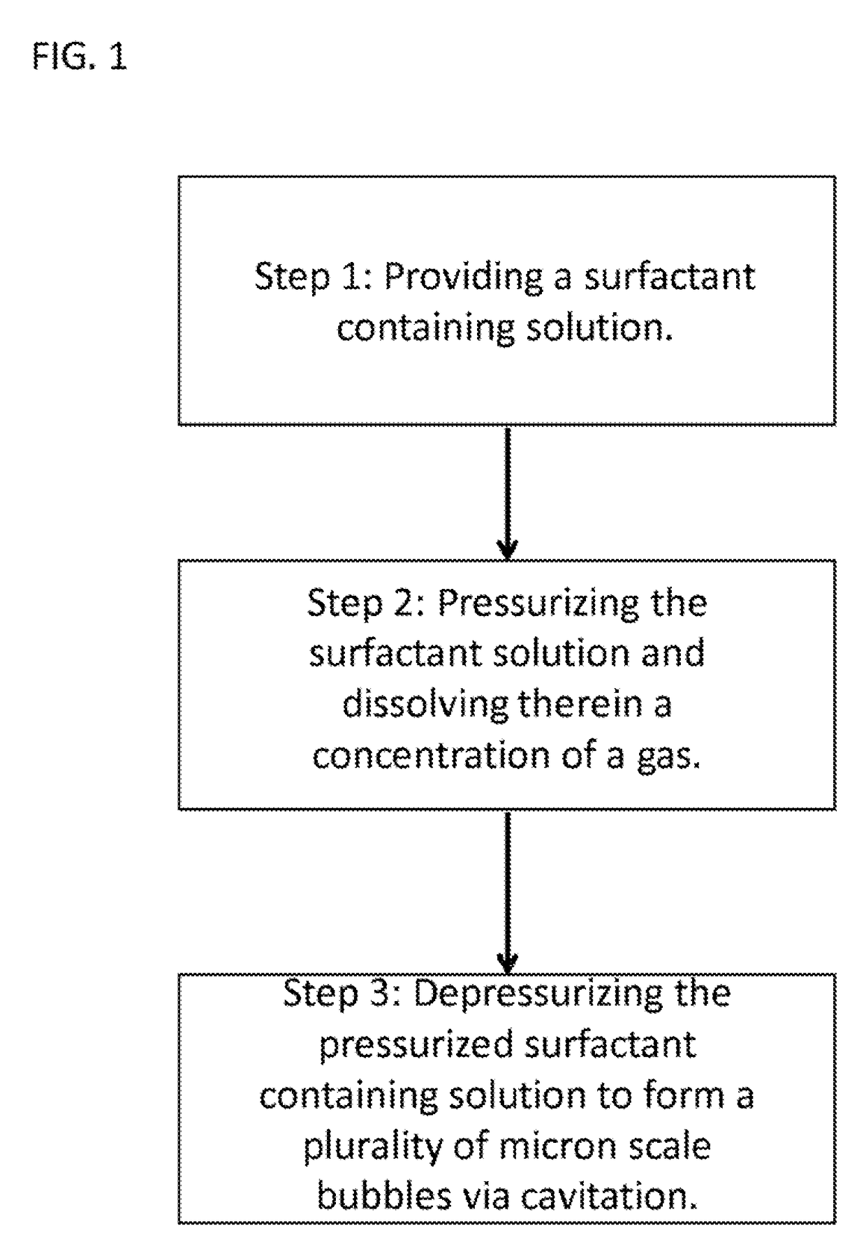
The invention is about a method and device for making small bubbles of liquid with surfactants. The device works by pressurizing a solution containing a surfactant and then releasing it through a small nozzle to create bubbles. The pressure difference between the solution and the environment where it is released helps to break the solution open and form bubbles. The bubbles generated are small, stable, and can live for at least 10 minutes. The technical effect of this invention is that it allows for the creation of stable bubbles in a simple and efficient way.

Problems solved by technology

However, a bubble made with a pure liquid alone is not stable and a dissolved surfactant such as soap is needed to stabilize a bubble.
At extremely small sizes, such as on the order of microns, it is difficult to manufacture a frame with small enough orifices to reliably generate the desired size and shape of bubbles.

Method used


Image

  • Method and Apparatus for the Production of Microscale Bubbles by Depressurization Cavitation
  • Method and Apparatus for the Production of Microscale Bubbles by Depressurization Cavitation
  • Method and Apparatus for the Production of Microscale Bubbles by Depressurization Cavitation

Examples


example 1

essor Device

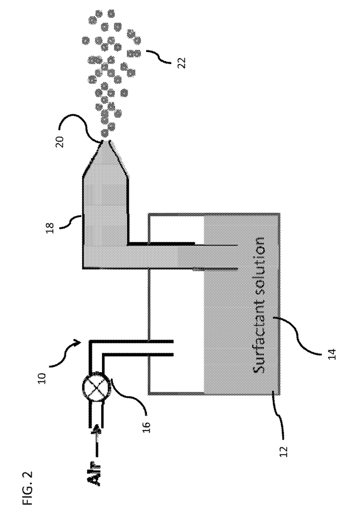
[0033]FIG. 2 shows a schematic of a spray nozzle bubble generation system in accordance with the current invention. As discussed above, while this example provides an embodiment of the invention, it should be understood that other apparatuses that incorporate the pressurizing and depressurizing system described above would be incorporated into this invention, and that this specific embodiment is provided only to demonstrate the feasibility of the inventive system in producing neutrally buoyant bubbles in the 10 micron size range.

[0034]As shown in the diagram of FIG. 2, in this embodiment the bubble generation device (10) of the instant invention comprises a reservoir (12) for containing a surfactant solution (14) that can be pressurized to a desired level. By pressurizing the solution air is forced into the solution in accordance with Henry's Law:

p=kHc  EQ. 2

where p is the partial pressure of the solute in the gas above the solution, c is the concentration of the solute ...

example 2

Piston Device

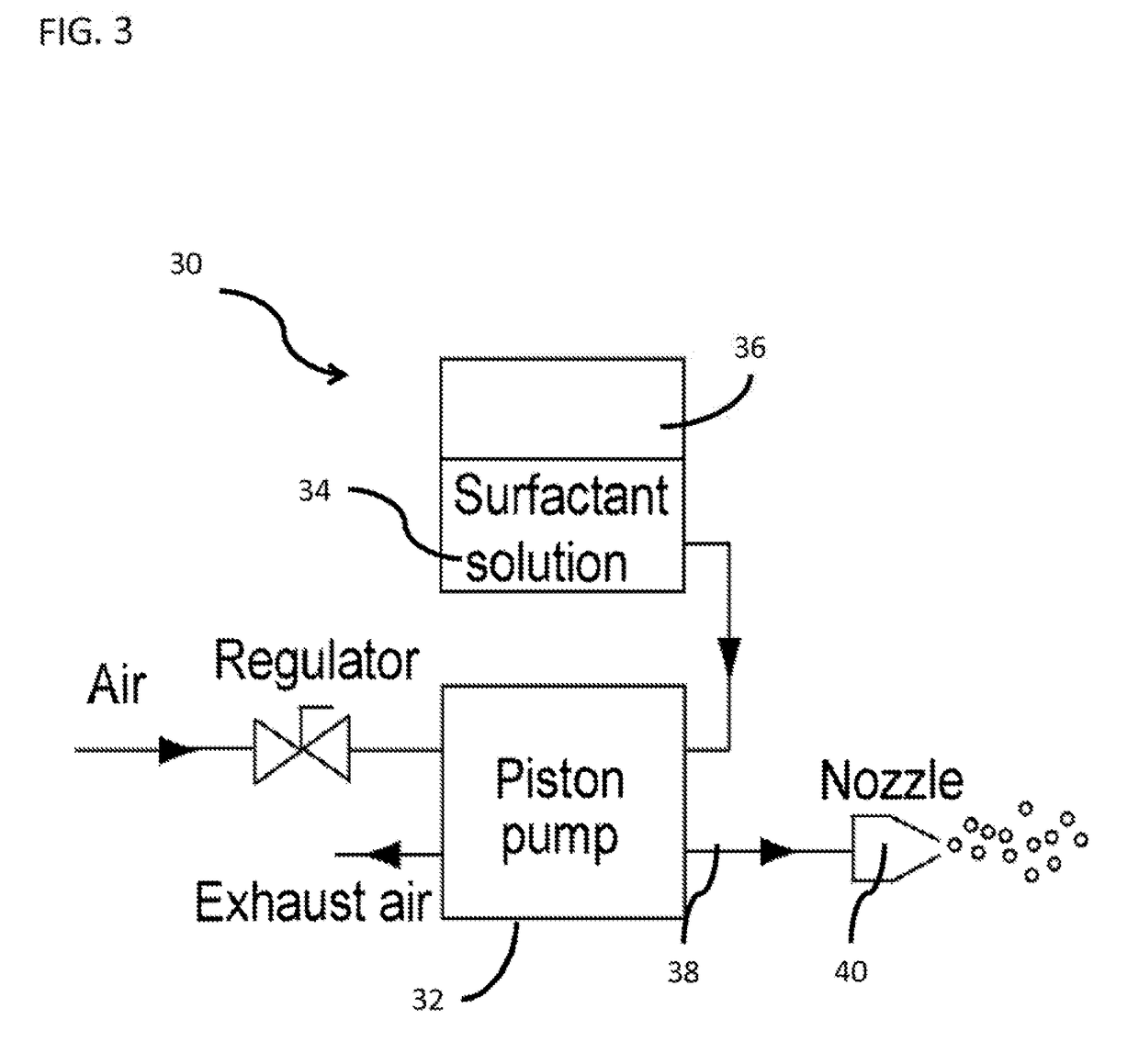
[0038]Although one embodiment of the invention is provided above, it should be understood that other methods of pressurizing and depressurizing the surfactant solution may be developed. For example, FIG. 3 provides a schematic of another embodiment of the bubble-generator (30). In this embodiment, a pneumatic driven piston pump (32) (M-series, Haskel Inc.) pressurizes soap solution (34). The soap solution in a reservoir tank (36) enters the liquid inlet (38) of the piston pump, and it is pressurized by the piston pump. When the pressurized solution passes through a misting nozzle (40) having a specific orifice size, it is atomized by an atomizer inside the nozzle and depressurized by a constricting area of the nozzle.

[0039]As before, the mechanism of bubble generation for this device is a cavitation process in liquid media. The basic concept is the rapid depressurization of an already pressurized liquid containing a desired amount of surfactant below its vapor or gas pa...


PUM


Abstract

A method and apparatus that enables the production of micron-scale free-standing bubbles made of liquids containing surfactants are provided. The method and apparatus of the invention overcomes the limitations of conventional bubble forming techniques by using a controlled cavitation process in a liquid media.

Description

CROSS-REFERENCE TO RELATED APPLICATIONS[0001]The current application is a continuation of U.S. application Ser. No. 13 / 089,910, filed Apr. 19, 2011, which application claims priority to U.S. Provisional Application No. 61 / 325,881, filed Apr. 20, 2010, the disclosures of which are incorporated herein by reference in their entireties.FIELD OF THE INVENTION[0002]The current invention is directed to a method and apparatus for the production of micron-scale free-standing bubbles; and more particularly to bubbles made of liquids containing surfactants.BACKGROUND OF THE INVENTION[0003]A free-standing bubble is a very thin film of surfactant containing fluid (such as soapy water) that forms a sphere. Such surfactant containing bubbles usually last for only a few seconds before bursting, either on their own or on contact with another object. Such surfactant bubbles can help solve complex mathematical problems of space, as they will always find the smallest surface area between points or edge...

Claims


Application Information

Patent Timeline
Patent Type & Authority Applications(United States)
IPC IPC(8): A61M11/00B05B7/00
CPCA61M11/007B05B7/0018A61M2202/0468A61M11/00
Inventor GHARIB, MORTEZAKIM, DAEGYOUM
Owner CALIFORNIA INST OF TECH
Learn More