
Hydrodynamic cavitation strengthening equipment

A hydraulic cavitation and equipment technology, applied in the field of cavitation, can solve problems such as low input energy, small change in liquid flow rate, and difficulty in efficient application

Inactive Publication Date: 2021-03-26
TSINGHUA UNIV
View PDF13 Cites 0 Cited by
  • Summary
  • Abstract
  • Description
  • Claims
  • Application Information

AI Technical Summary

Problems solved by technology

Except for hydrodynamic cavitation, the other three are difficult to be efficiently applied in large-scale industrial production due to low input energy and limited action space.
[0004] The current geometric structure of the system changes the flow rate of the liquid through the setting of the spiral parts or the vibration of the vibrating reed, thereby generating cavitation, but the above structure can only drive the local liquid, and the change of the flow rate of the liquid is small, and the efficiency of cavitation is poor. , leading to poor utilization efficiency of cavitation effect

Method used


Image

  • Hydrodynamic cavitation strengthening equipment
  • Hydrodynamic cavitation strengthening equipment
  • Hydrodynamic cavitation strengthening equipment

Examples


Embodiment Construction

[0027] Embodiments of the present invention are described in detail below, examples of which are shown in the drawings, wherein the same or similar reference numerals designate the same or similar elements or elements having the same or similar functions throughout. The embodiments described below by referring to the figures are exemplary and are intended to explain the present invention and should not be construed as limiting the present invention.

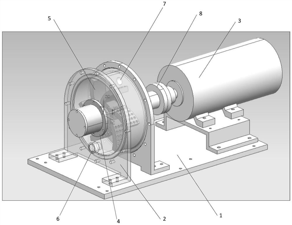
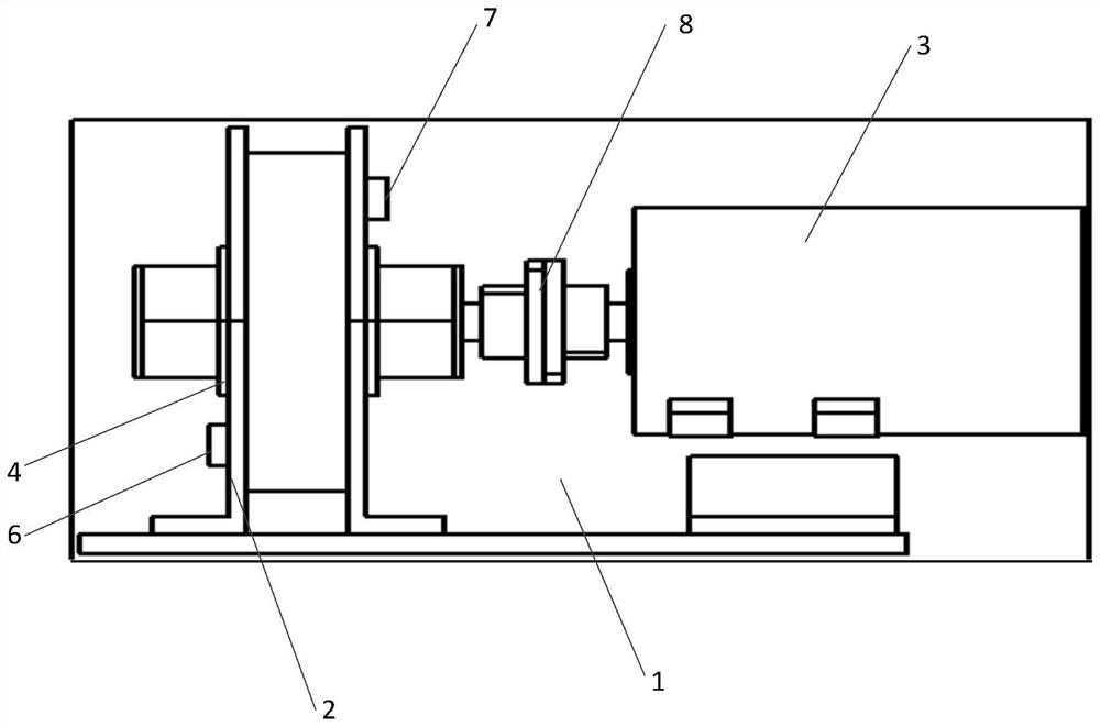
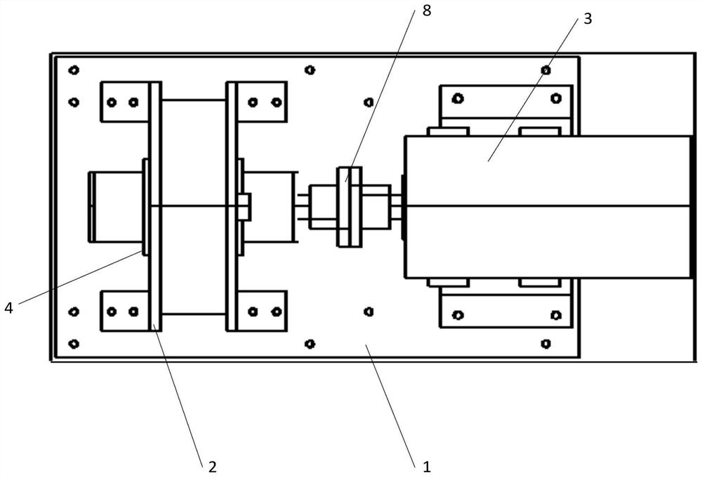
[0028] Refer to the attached Figure 1-Figure 6 A hydrodynamic cavitation strengthening device according to an embodiment of the present invention will be described.

[0029] Such as Figure 1-Figure 6 As shown, the hydraulic cavitation strengthening equipment according to the embodiment of the present invention includes:

[0030] The base bracket 1, the flange group and the motor 3 arranged on the base bracket 1, the two flanges 2 of the flange group form a cavity, and the centers of the two flanges 2 are respectively provided...


PUM


Abstract

The invention discloses hydrodynamic cavitation strengthening equipment, which comprises a base bracket, a flange set and a motor, wherein the flange set and the motor are arranged on the base bracket, a cavity is formed by two flanges of the flange set, sealing rings are arranged in the centers of the two flanges respectively, a blade set is arranged between the two sealing rings in a clamped mode, an inlet pipe is arranged on the flange far away from the motor, an outlet pipe is arranged on the flange close to the motor, and the shaft of the blade set penetrates through the two sealing ringsand is fixedly connected with the shaft of the motor through a coupler so as to be driven by the motor to rotate. According to the invention, a liquid in the cavity can be subjected to shearing, rubbing, centrifugation, turbulence and the like through rotation and cutting of the blade set to drive all the liquid in the cavity to flow, so that the flow speed of the liquid in the cavity is promotedto be greatly changed, the pressure of the liquid in the cavity is promoted to be changed, the cavitation process is intensified, and the cavitation generation efficiency and the cavitation effect utilization efficiency are improved.

Description

technical field [0001] The invention relates to the technical field of cavitation, in particular to hydraulic cavitation strengthening equipment. Background technique [0002] Cavitation is a process of forming vapor cavitation in the low-pressure area of ​​the liquid flow field. When the internal pressure of the liquid drops below the saturated vapor pressure, the bubbles formed in the cavitation process begin to appear and grow. As time goes on, the cavitation Dilation, growth, compression and collapse. This process is explosive, less than six thousandths of a second, and the cavitation can release huge energy at the moment of rapid collapse, instantly generating local high temperature (1900-5000K) and high pressure (up to 140MPa-170Mpa), and the generation speed is about 110m / s micro-jet with powerful impact, thus causing a series of phenomena such as cavitation, air noise, vibration and luminescence. These effects caused by cavitation are usually called cavitation effec...

Claims


Application Information

Patent Timeline
Patent Type & Authority Applications(China)
IPC IPC(8): B01J19/18
CPCB01J19/18B01J19/0053B01J19/0066
Inventor 张伟谭磊
Owner TSINGHUA UNIV
Learn More