
Processing method of detection pipe

A processing method and a technology for detecting tubes, which are applied in the field of pipe fittings processing, can solve the problems of increasing the processing time of pipe fittings, offsetting the fixed position of the fixed plate, and increasing the occupied area of ​​equipment, so as to increase processing efficiency, increase position accuracy, reduce The effect of footprint

Active Publication Date: 2022-07-26
浙江长兴和良智能装备有限公司
View PDF5 Cites 0 Cited by
  • Summary
  • Abstract
  • Description
  • Claims
  • Application Information

AI Technical Summary

Problems solved by technology

[0002] When conventional pipe fittings are sealed, they need to be welded to seal and fix the sealing of the pipe fittings. However, the existing welding operation is usually done manually, which increases a lot of labor costs and reduces the efficiency of pipe fitting sealing.
[0003] At the same time, when the existing pipe fittings perform a series of other processes such as pipe bending and setting of fixed plates, the pipe fittings are usually processed sequentially by multiple single-process equipment, and multiple single-process equipment will greatly increase the equipment capacity. Occupy an area, and increase the transportation time of pipe fittings between each single process equipment, thereby increasing the time of pipe fitting processing
[0004] In addition, in the process of installing the fixing plate on the pipe fittings, the fixing plate is usually manually placed on the pipe fittings for fixing, and it is inevitable that the positioning position of the fixing plate is inaccurate and the fixing position of the fixing plate is shifted due to manual operation. The situation, which in turn leads to the unreliable stability of the fixing plate on the pipe fittings

Method used


Image

  • Processing method of detection pipe
  • Processing method of detection pipe
  • Processing method of detection pipe

Examples


Embodiment Construction

[0037] The technical solutions in the embodiments of the present invention will be clearly and completely described below with reference to the accompanying drawings in the embodiments of the present invention. Obviously, the described embodiments are only a part of the embodiments of the present invention, but not all of the embodiments. All other embodiments obtained by those of ordinary skill in the art based on the embodiments of the present invention fall within the protection scope of the present invention.

[0038] It should be understood by those skilled in the art that in the disclosure of the present invention, the terms "portrait", "horizontal", "upper", "lower", "front", "rear", "left", "right", " The orientation or positional relationship indicated by vertical, horizontal, top, bottom, inner, outer, etc. is based on the orientation or positional relationship shown in the accompanying drawings, which are only for the convenience of describing the present invention a...


PUM


Abstract

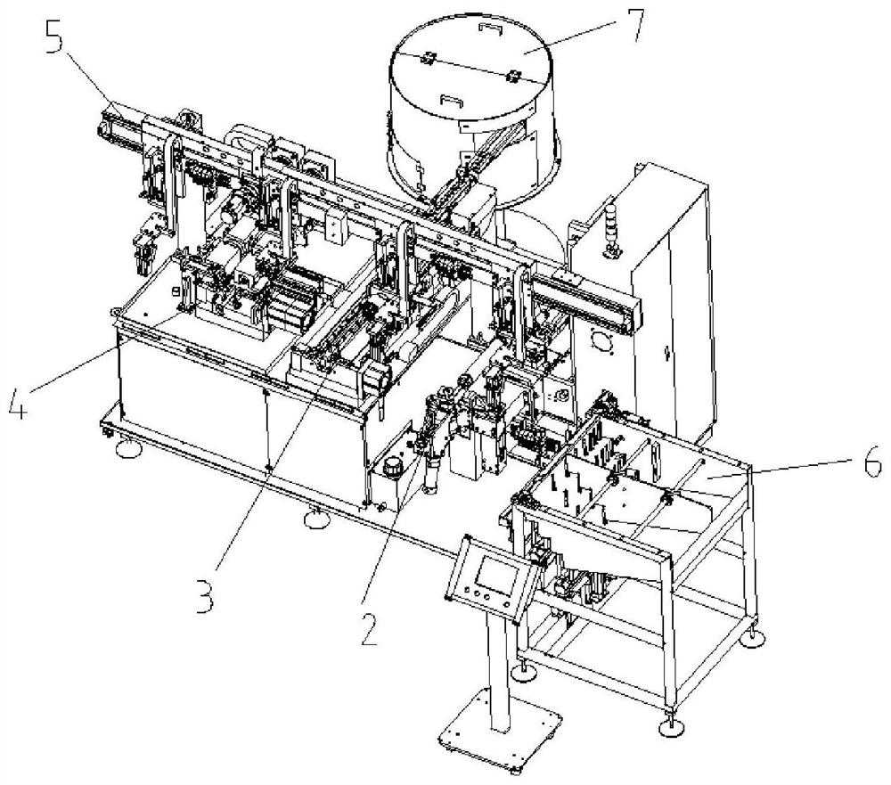
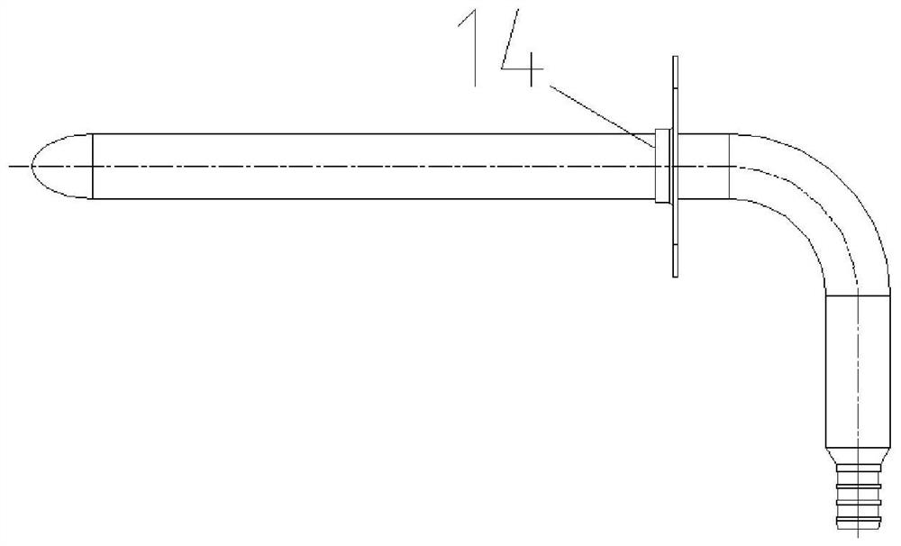
The invention provides a machining method of a detection pipe. The machining method comprises the following steps that a pipe fitting is bent; the pipe fitting obtained after pipe bending is completed is moved to a fixing plate feeding component in a fixing plate mounting device, and the axis of the pipe fitting is made to coincide with the axis of a mounting hole in a fixing plate; the first core rod sequentially penetrates through the mounting hole of the fixing plate and the interior of the pipe fitting, and then the fixing plate moves along the first core rod and is arranged on the outer side of the pipe fitting in a sleeving mode; the pipe fitting sleeved with the fixing plate is moved to a dotting station, and a fixing ring on one side of the fixing plate is fixed to the pipe fitting through a second core rod and a plurality of dotting dies; performing necking treatment and sealing treatment on the to-be-processed end of the pipe fitting; the pipe fitting obtained after sealing machining is completed is moved to a discharging area through a translation device; when the to-be-machined end of the pipe fitting is sealed, the pipe fitting does not need to be welded and sealed, the pipe fitting machining efficiency is improved, and the labor cost and the equipment occupied area are reduced.

Description

technical field [0001] The invention relates to the technical field of pipe fitting processing, in particular to a processing method of a detection tube. Background technique [0002] When sealing a conventional pipe fitting, it is necessary to seal and fix the sealing part of the pipe fitting by welding, and the existing welding operation is usually performed manually, which increases a lot of labor costs and reduces the sealing efficiency of the pipe fitting. [0003] At the same time, when the existing pipe fittings are subjected to a series of processes such as pipe bending and setting of fixed plates, the pipe fittings are usually processed sequentially by multiple single-process equipment, and multiple single-process equipment will greatly increase the number of equipment. space, and increase the transportation time of pipe fittings between each single process equipment, thereby increasing the processing time of pipe fittings. [0004] In addition, in the process step...

Claims


Application Information

Patent Timeline
Patent Type & Authority Applications(China)
IPC IPC(8): B21D7/022B21D39/00B21D41/04
CPCB21D7/022B21D39/00B21D41/045Y02E30/30
Inventor 王元宾许春涛杨正法李周鲜崔国杰邓云
Owner 浙江长兴和良智能装备有限公司
Learn More