Partition wallboard base

A technology of wall panels and side panels, applied in the field of partition wall panel bases, can solve the problems of reduced support and fixing effect of partition wall panels, complex base structure, reduced tank stability, etc. Integrity and use stability assurance, the effect of reducing processing costs

Pending Publication Date: 2022-07-22
江苏爱拼环保科技有限公司
View PDF0 Cites 0 Cited by
  • Summary
  • Abstract
  • Description
  • Claims
  • Application Information

AI Technical Summary

Problems solved by technology

In the first form, the structure of the entire base is complicated due to the integration of the arc-shaped transition part into the tank body, and the production is difficult. At present, there is no fully integrated stainless steel partition wall base. What can be realized at present is to divide the base into left and right parts. The pieces are prepared separately, and then connected with each other by connecting plates. This method causes the tank body to be divided, the stability of the tank body is reduced, and the support and fixing effect of the entire base on the partition wall panel is reduced.
[0006] The technical solution currently used in the second form is to make the arc-shaped transition part into the form of a base, and then connect the tank to the top of the base to form a complete partition wall base. This structure results in a large overall height of the base and a large amount of materials. Large, and the construction site welding is required between the base and the tank body. The large amount of welding will easily cause welding deformation of the base, and the small amount of welding will lead to poor connection stability.

Method used


Image

  • Partition wallboard base
  • Partition wallboard base
  • Partition wallboard base

Examples


Embodiment 1

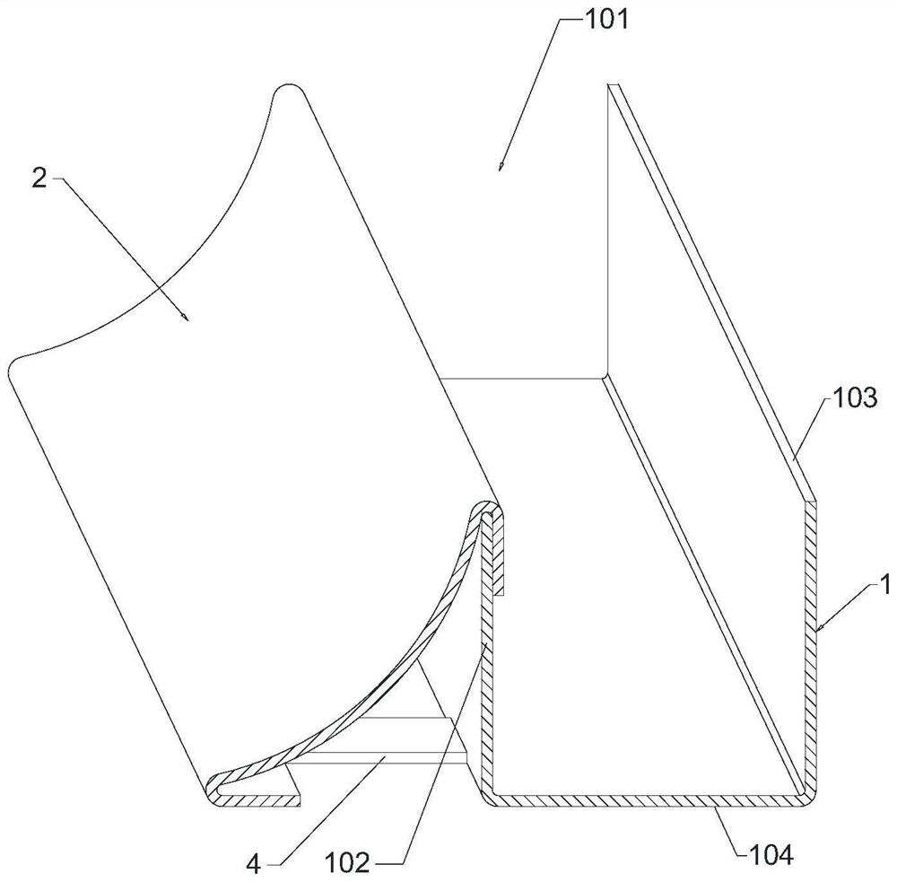
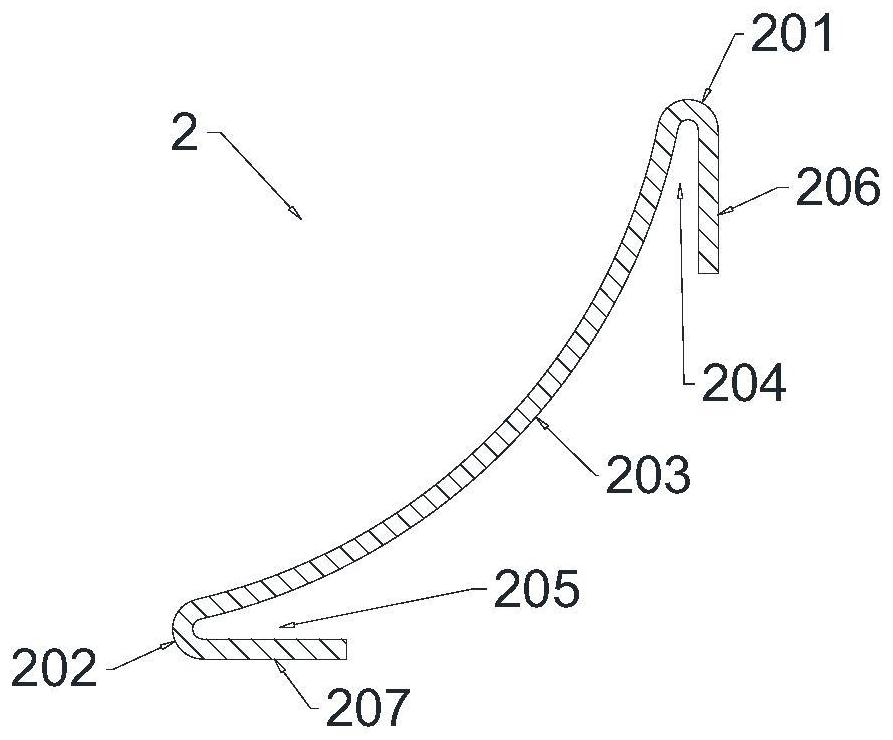
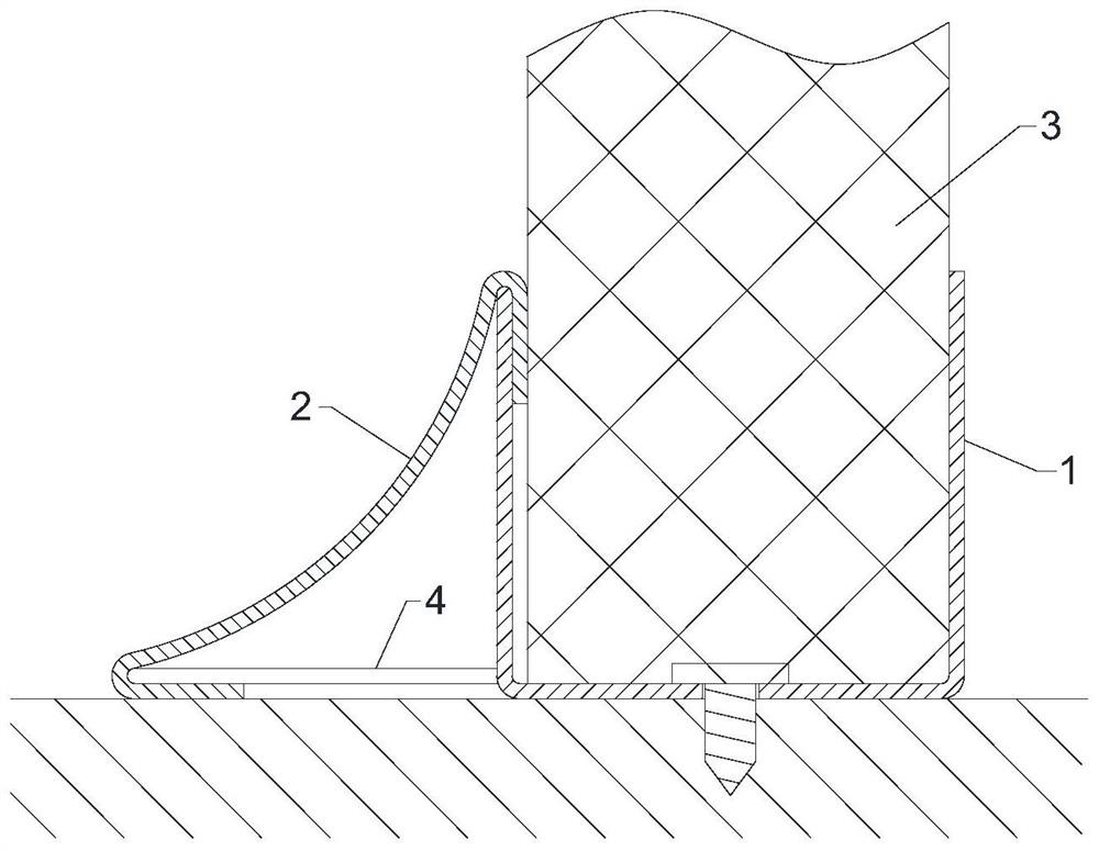
[0032] like Figures 1~6 The base of the partition wall panel shown is preferably made of corrosion-resistant, high-strength metal materials such as stainless steel. It includes a U-shaped groove body 1 that opens upward and a first transition plate 2 connected to one side of the groove body 1. The U-shaped groove 101 at the upper end of the groove body 1 is used for inserting the wall plate 3, and both sides of the U-shaped groove 101 are used. They are the first side plate 102 and the second side plate 103 of the tank body 1 respectively. The bottom of the U-shaped groove 101 is the bottom plate 104 connecting the first side plate 102 and the second side plate 103. The first transition plate 2 is obliquely arranged in the groove. The outer side of the body 1 is used to connect the first side plate 102 of the tank body 1 and the ground. like figure 2 As shown, the upper part of the first transition plate 2 is bent toward its back along a bending line parallel to the axial ...

Embodiment 2

[0046] like Figure 7 and Figure 8 As shown, the partition wall panel base shown in this embodiment includes a U-shaped groove body 1 opening upward and a first transition plate 2 connected to one side of the groove body 1. The U-shaped groove 101 at the upper end of the groove body 1 is used for In the plug-in wall panel 3, the two sides of the U-shaped groove 101 are the first side plate 102 and the second side plate 103 of the tank body 1 respectively, and the bottom of the U-shaped groove 101 is the connection between the first side plate 102 and the second side plate 103. The bottom plate 104, the first transition plate 2 is obliquely arranged on the outside of the tank body 1, and is used to connect the first side plate 102 of the tank body 1 and the ground. The upper part of the first transition plate 2 is bent toward its back along a bending line parallel to the axial direction of the groove body to form an arc-shaped first upper bending part 201 and a straight first...


PUM


Abstract

The base comprises a U-shaped groove body with an upward opening and a first transition plate connected to one side of the groove body, and the first transition plate is tightly matched with the base in a clamping mode, so that the welding cost is greatly reduced, the height of the base can be effectively reduced, and the welding quality is improved. The stability of the whole structure is improved. In the aspect of installation, the installation process of the base is simple, the base is independently installed without field welding, the installation speed is effectively increased, and the installation cost is reduced.

Description

technical field [0001] The invention relates to a partition wall board base. Background technique [0002] The base of the partition wall panel is mainly used for indoor partition decoration. [0003] In food processing workshops, drug production workshops and electronic product production vehicles that have high requirements on the cleanliness of the working environment, stainless steel partition wall panel bases are usually used, because the stainless steel partition wall panel base is resistant to acid, alkali and oxidation. , It can be used for a long time without generating impurities, and at the same time, it is easy to clean and can be kept clean for a long time. Therefore, for partition decoration in workshops that have high requirements on the cleanliness of the working environment, the base of the partition wall panel made of stainless steel is better than that of aluminum alloy. [0004] Because it is used in a clean working environment, the base of the partitio...

Claims


Application Information

Patent Timeline
IPC IPC(8): E04B2/82E04B2/74E04B1/38E04B1/66
CPCE04B2/82E04B2/74E04B2/827E04B1/66E04B1/38
Inventor 杜为山陈猛
Owner 江苏爱拼环保科技有限公司
Why Eureka
Try Eureka