
Thin-wall metal selective magnetic vibration stirring friction welding device and welding method

A friction welding and vibration stirring technology, used in welding equipment, metal processing equipment, non-electric welding equipment, etc., can solve the problems of difficult to achieve high-frequency induced current, uncontrollable force direction, uncontrollable current path, etc. It is beneficial to the grain refinement of the weld structure, low cost, and the effect of improving the welding quality

Pending Publication Date: 2022-07-22
JIANGSU UNIV OF SCI & TECH +1
View PDF1 Cites 0 Cited by
  • Summary
  • Abstract
  • Description
  • Claims
  • Application Information

AI Technical Summary

Problems solved by technology

If the permanent magnet is used to move perpendicular to the direction of the workpiece to produce electromagnetic induction heating effect, it is difficult to achieve high-frequency induced current while still acting on the local area; if the workpiece is energized to make the metal in the welding area move under the force of the magnetic field, there Safety issues, and the uncontrollable current path on the workpiece leads to uncontrollable force direction
If the method of rotating magnets is used to generate a rotating magnetic field, only magnets with smaller masses and lower rotation speeds can be used

Method used


Image

  • Thin-wall metal selective magnetic vibration stirring friction welding device and welding method
  • Thin-wall metal selective magnetic vibration stirring friction welding device and welding method
  • Thin-wall metal selective magnetic vibration stirring friction welding device and welding method

Examples


Embodiment Construction

[0038] The following describes in detail the embodiments of the present invention, examples of which are illustrated in the accompanying drawings, wherein the same or similar reference numerals refer to the same or similar elements or elements having the same or similar functions throughout. The embodiments described below with reference to the accompanying drawings are exemplary, only used to explain the present invention, and should not be construed as a limitation of the present invention.

[0039]In the description of the present invention, it should be understood that the orientation or positional relationship indicated by the terms "center", "upper", "lower", "front", "rear", "left", "right", etc. is based on the attached The orientation or positional relationship shown in the figures is only for the convenience of describing the present invention and simplifying the description, rather than indicating or implying that the indicated combination or element must have a spec...


PUM


Abstract

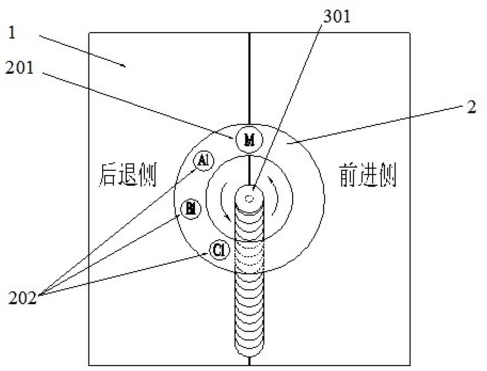
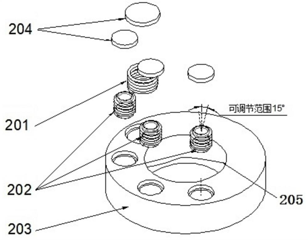
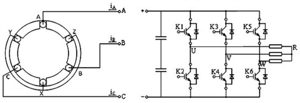
The invention discloses a thin-wall metal selective magnetic vibration stirring friction welding device which comprises a stirring head driven by a spindle of a rotating motor and a pulsating magnetic field generator fixed to the stirring head. A high-frequency induction line heating coil M and a three-phase coil module are arranged at the end, facing the to-be-welded thin-wall metal part, of the pulsating magnetic field generator, so that a welding area of the thin-wall metal part is heated and a high-frequency vibration magnetic field is provided; and the three-phase coil module is provided with three independent power supplies A, B and C of which the phase difference is 120 degrees in sequence, and the phase sequence and the frequency of the three-phase power supplies A, B and C are adjustable. According to the magnetic vibration stirring friction welding device and the welding method thereof, the temperature uniformity in the welding circumferential direction of the thin-wall metal part and the uniformity of a pulsating magnetic field are guaranteed, weld joint structure grains are evenly refined, the welding performance of the thin-wall metal part is remarkably improved, continuous operation can be conducted, a long-size to-be-welded part can be prepared, and the welding quality is improved. And the yield is improved.

Description

technical field [0001] The invention relates to the technical field of thin-walled metal welding equipment and methods, in particular to a thin-walled metal selective magnetic vibration friction stir welding device and a welding method. Background technique [0002] During friction stir welding of thin-walled metals, the pressing amount of the stirring head is small, the rotational speed is small, and the volume of the plasticized metal is also small. The metal on the retreating side often causes flash or tunnel defects in the weld due to the untimely flow of the metal. At the same time, due to the insufficient friction and extrusion effect of the stirring head, the heat generation is low, the resistance of the stirring needle is large, and even the stirring needle is broken and the welding fails. In this way, supplementing auxiliary energy has become an inevitable choice. [0003] Many researchers at home and abroad have carried out related research on this. Most of the au...

Claims


Application Information

Patent Timeline
Patent Type & Authority Applications(China)
IPC IPC(8): B23K20/12B23K20/26
CPCB23K20/122B23K20/1245
Inventor 陈鑫毅陈书锦罗建坤陈树君孙宏伟刘超张本顺方臣富高阳
Owner JIANGSU UNIV OF SCI & TECH
Learn More