
Patsnap Eureka
For R&D, Patsnap Eureka makes reading and utilizing patents & technical documents easy.
Patsnap Eureka AIR
Designed for self-driven R&D workflows. Generate viable solutions, solve complex R&D challenges, empower your innovation with AI.

Patsnap Eureka Materials
Designed for material experts only. Revolutionize your material R&D, from search, analyze, to developing new materials.

TechResearch
Generate reliable direction feasibility study reports for your R&D in just a few steps.

TechSeek
Discover and master advanced knowledge NOW. Basics, ideas, possibilities, all at once.

TechMind
As an expert in R&D Theories, TechMind can generates customized viable solutions instantly.

TechRisk
Analyze your overall solution with one click, know your potential R&D risks in advance.

TechMonitor
Get weekly tech updates, stay abreast of the latest tech innovations and key insights.
Efficient wheat cleaning device for flour production
A cleaning device and wheat technology, applied in the direction of cleaning methods using liquids, cleaning methods using tools, cleaning methods and utensils, etc., can solve the problems of low cleaning efficiency and low friction, improve environmental protection performance, and accelerate cleaning speed , Convenient loading and unloading effect
- Summary
- Abstract
- Description
- Claims
- Application Information
AI Technical Summary
Problems solved by technology
Method used
Image

Examples
Embodiment 1
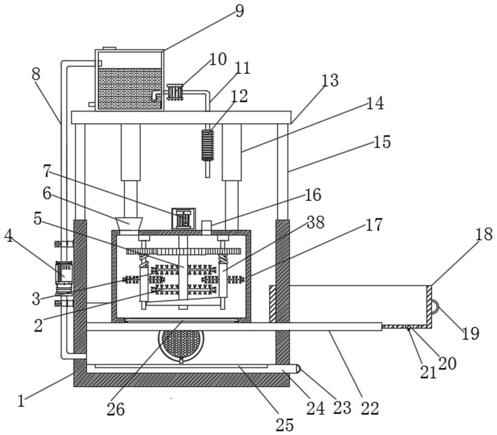
[0029] A high-efficiency wheat cleaning device for flour production, comprising a cleaning box 17, a first rotating shaft 5 is arranged inside the cleaning box 17, an electric motor 7 is arranged on the upper end of the first rotating shaft 5, and the electric motor 7 is fixed on the upper end of the cleaning box 17, The upper end of the cleaning box 17 is provided with a feeding port 6, a water inlet 16 is provided on one side of the feeding port 6, and a plurality of groups of first stirring rods 2 are provided on the surface of the first rotating shaft 5, and the surface of the first stirring rod 2 is provided with Multiple groups of first brushes 3, stirring components 37 are provided on both sides of the first stirring rod 2;
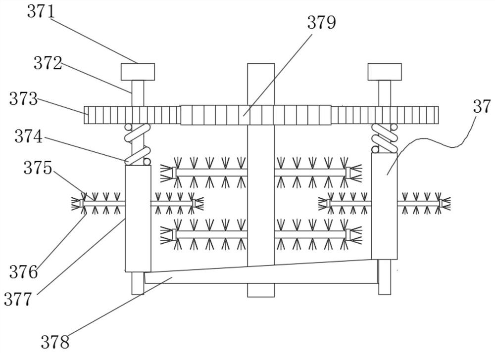
[0030] The stirring assembly 37 includes a second gear 379 fixed on the outside of the first rotating shaft 5 , the two sides of the second gear 379 are provided with a first gear 373 that meshes with the second gear 379 , and a second gear 373 is p...
Embodiment 2
[0033] As an optional case, see Figure 1-2 , an efficient wheat cleaning device for flour production. The outside of the cleaning box 17 is provided with a box 1, and the inside of the box 1 is provided with a support frame 22. One end of the support frame 22 extends through the box body 1 and extends to the outside. At the bottom of the cleaning box 17, the inner bottom of the box body 1 is provided with a clean water tank 30, the upper end of the box body 1 is provided with a support rod 15, the upper end of the support rod 15 is provided with a fixing plate 13, and the upper end of the fixing plate 13 is provided with a water tank 9. The outside of the water tank 9 is provided with a water pump 10, the water inlet pipe 11 connected to the inlet end of the water pump 10 extends into the interior of the water tank 9, the water inlet pipe 11 connected to the outlet end of the water pump 10 is aligned with the water inlet 16, and the water inlet pipe 11 is connected with The c...
Embodiment 3
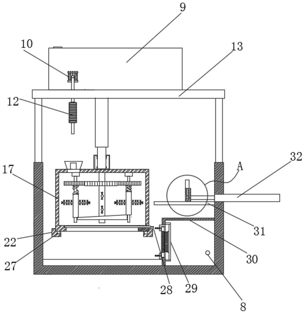
[0037] As an optional case, see Figure 1-2 , Image 6 , a high-efficiency wheat cleaning device for flour production. The bottom of the cleaning box 17 is provided with a through port, and a discharge plate 26 is arranged in the through port. The discharge plate 26 runs through one end of the cleaning box 17 and is provided with a frame 28. 28 is provided with a support plate 31 on the inner wall of one side, the upper end of the support plate 31 is provided with a slider 35, the upper end of the slider 35 is provided with an electric push rod 36, and the output end of the electric push rod 36 is provided with a stopper 33, the slider 35 is provided with a limit slot 34 on the side close to the frame 28, the stopper 33 is arranged inside the limit slot 34, and the side of the slider 35 away from the frame 28 is connected with the output end of the second electro-hydraulic push rod 32, the cleaning box 17 The upper end is provided with a first electro-hydraulic push rod 14, t...
PUM
 Abstract
Description
Claims
Application Information
 - R&D Engineer
- R&D Manager
- IP Professional
- Industry Leading Data Capabilities
- Powerful AI technology
- Patent DNA Extraction
Browse by: Latest US Patents, China's latest patents, Technical Efficacy Thesaurus, Application Domain, Technology Topic, Popular Technical Reports.
© 2024 PatSnap. All rights reserved.Legal|Privacy policy|Modern Slavery Act Transparency Statement|Sitemap|About US| Contact US: help@patsnap.com