Eureka AIR delivers breakthrough ideas for toughest innovation challenges, trusted by R&D personnel around the world.

Method and device for removing multi-component pollutants in flue gas based on supergravity technology

A multi-component and pollutant technology, applied in the field of flue gas purification, can solve the problems of increasing system operating costs and low activation efficiency, and achieve the effect of small footprint, low cost and resource reuse

Pending Publication Date: 2022-07-22
ZHONGBEI UNIV
View PDF3 Cites 0 Cited by
  • Summary
  • Abstract
  • Description
  • Claims
  • Application Information

AI Technical Summary

Problems solved by technology

However, thermal activation is an activation method with low activation efficiency. In order to achieve a high denitration rate, this requires the dual oxidant in the liquid phase to maintain a high concentration, which increases the operating cost of the system.

Method used

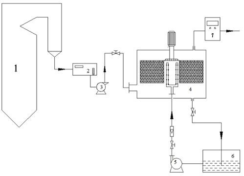
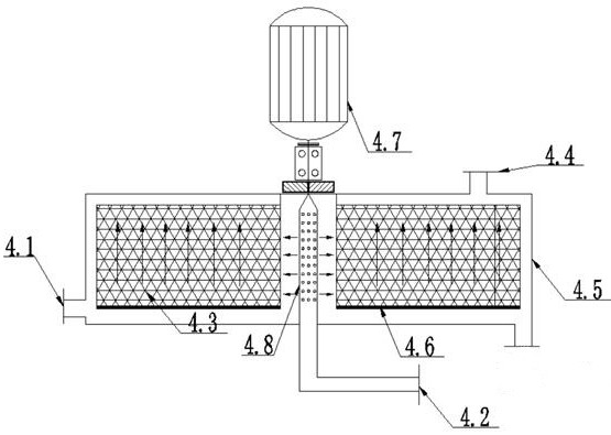

Image

  • Method and device for removing multi-component pollutants in flue gas based on supergravity technology
  • Method and device for removing multi-component pollutants in flue gas based on supergravity technology
  • Method and device for removing multi-component pollutants in flue gas based on supergravity technology

Examples


preparation example Construction

[0057] The described filler for enhancing gas-liquid mass transfer is specifically prepared by the following method:

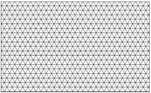
[0058] (1) The filler is composed of metal wires, and the metal wires are arranged in a cross to form a mesh of diamond-shaped holes, and the area of ​​the diamond-shaped holes is about 0.6~0.8cm 2 .

[0059] (2) In the radial direction, the cross-arranged metal wires are corrugated.

[0060] (3) Roll the wire mesh with the above structure into cylinders with different diameters, leaving a gap of 2-3 mm between the two cylinders, and then fix them on the lower tray of the filler.

Embodiment 1

[0063] Preparation of absorption liquid, specific components: (NH 4 ) 2 S 2 O 8 Concentration is 0.2 mol / L, H 2 O 2 Concentration of 0.3 mol / L, FeSO 4 Concentration of 0.01 mol / L, CuSO 4 The concentration is 0.01 mol / L. Turn on the hypergravity machine and set the hypergravity factor to 70. The absorbing liquid was injected into the rotating packed bed from the liquid inlet using a centrifugal pump, and the liquid flow rate was 100 L / h. The NO gas injection machine is in full contact with the liquid, and the gas flow rate is 1000 L / h. NO, SO 2 , Hg 0 The removal rates were 76.25%, 95.43% and 75.85%, respectively.

Embodiment 2

[0065] Preparation of absorption liquid, specific components: (NH 4 ) 2 S 2 O 8 Concentration is 0.5 mol / L, H 2 O 2 Concentration of 0.8 mol / L, FeSO 4 Concentration of 0.08 mol / L, CuSO 4 The concentration is 0.08 mol / L. Turn on the hypergravity machine and set the hypergravity factor to 90. The absorbing liquid was injected into the rotating packed bed from the liquid inlet using a centrifugal pump, and the liquid flow rate was 100 L / h. The NO gas injection machine is in full contact with the liquid, and the gas flow rate is 1000 L / h. NO, SO 2 , Hg 0 The removal rates were 80.13%, 96.38% and 77.48%, respectively.


PUM

PropertyMeasurementUnit
Hole areaaaaaaaaaaa

Abstract

The invention discloses a method and a device for removing multi-component pollutants in flue gas based on a supergravity technology, and the method is characterized in that NOx, SO2 and Hg < 0 > pollutants in the flue gas are synchronously removed by using a multi-component absorption liquid under the condition of a supergravity rotating packed bed; and the absorption liquid and the flue gas are in cross-flow contact in a high gravity field, so that the aim of synchronously removing multi-component pollutants in the flue gas is fulfilled. The supergravity rotating packed bed is composed of a shell, a filler for strengthening gas-liquid mass transfer, a filler base and a motor, the filler for strengthening gas-liquid mass transfer is composed of metal wires, the metal wires are arranged in a crossed mode to form a rhombic hole-shaped net, and the area of rhombic holes is 0.6-0.8 cm < 2 >; in the radial direction, the metal wires arranged in the crossed mode are in a corrugated shape. The supergravity rotating packed bed is used as a gas-liquid reaction place, so that the mass transfer process can be enhanced, and the removal efficiency of pollutants is greatly improved; the method has the advantages of being low in cost, good in economic performance, small in occupied area, capable of achieving resource recycling and the like.

Description

technical field [0001] The invention relates to a method and a device for removing multi-component pollutants in flue gas based on supergravity technology, and belongs to the field of flue gas purification. Background technique [0002] With the rapid development of industry, nitrogen oxides (mainly NO and NO) emitted from the combustion of fossil fuels 2 ) and sulfur dioxide (SO 2 ) air pollution is getting worse. At the same time, it can purify NO in exhaust gas x and SO 2 (sometimes also includes Hg in different flue gas sources 0 , H 2 S, VOCs, etc.) methods have received extensive attention. Currently commercial removal of SO 2 And NO technology mainly includes circulating fluidized bed technology (CFB), selective catalytic reduction (SCR) and wet flue gas desulfurization (WFGD) technology. However, there are still some shortcomings. For example, the CFB technology alone cannot meet the emission standards of pollutants, and the post-combustion flue gas treatment...

Claims


Application Information

Patent Timeline
IPC IPC(8): B01D53/78B01D53/96B01D53/60B01D53/64B01D53/56B01D53/50
CPCB01D53/78B01D53/96B01D53/60B01D53/64B01D53/56B01D53/50B01D2251/106B01D2251/10B01D2257/302B01D2257/404B01D2257/602B01D2258/0283
Inventor 祁贵生闫文超刘有智高雨松郭达
Owner ZHONGBEI UNIV
Why Eureka
Eureka Blog
Learn More