
Super-resolution method and device of laser radar, electronic equipment and storage medium

A laser radar and super-resolution technology, applied in the optical field, can solve the problems of high equipment cost, high complexity, and less research on super-resolution reconstruction technology, and achieve the effect of improving resolution and strong portability

Pending Publication Date: 2022-07-19
TSINGHUA UNIV
View PDF0 Cites 1 Cited by
  • Summary
  • Abstract
  • Description
  • Claims
  • Application Information

AI Technical Summary

Problems solved by technology

[0003] There are many existing technologies for the processing of lidar data alone and the super-resolution reconstruction of images, but there are few researches on the super-resolution reconstruction technology of lidar data
And in these technologies, most of them use the method of combining multi-frame images or combining 3D lidar data and 2D image data to achieve super-resolution reconstruction. There is no technology for direct super-resolution reconstruction on single-frame 3D lidar data, and there are Defects of high complexity, slow processing speed, and high equipment cost
More importantly, the super-resolution reconstruction of the existing technology is limited to the reconstruction to a specified high resolution, and cannot achieve the goal of reconstruction to an arbitrary resolution

Method used


Image

  • Super-resolution method and device of laser radar, electronic equipment and storage medium
  • Super-resolution method and device of laser radar, electronic equipment and storage medium
  • Super-resolution method and device of laser radar, electronic equipment and storage medium

Examples


Embodiment Construction

[0042] In order to make the objectives, technical solutions and advantages of the present invention clearer, the technical solutions in the present invention will be clearly and completely described below with reference to the accompanying drawings. Obviously, the described embodiments are part of the embodiments of the present invention. , not all examples. Based on the embodiments of the present invention, all other embodiments obtained by those of ordinary skill in the art without creative efforts shall fall within the protection scope of the present invention.

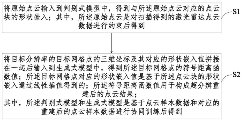
[0043] Combine below figure 1 Describe a super-resolution method of a lidar of the present invention, the method comprising:

[0044] S1. Input the original point cloud into the discriminant model, and obtain the shape embedding of the point cloud block corresponding to the original point cloud; wherein, the original point cloud is obtained by constraining the laser radar point cloud data obtained by scanning ; ...


PUM


Abstract

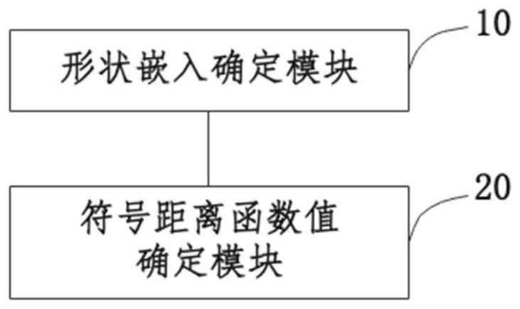
The invention provides a super-resolution method and device for a laser radar, electronic equipment and a storage medium, and the method comprises the steps: inputting an original point cloud into a discriminant model, and obtaining the shape embedding of a point cloud block corresponding to the original point cloud; the original point cloud is obtained by constraining laser radar point cloud data obtained by scanning; splicing the three-dimensional coordinates of the target grid points with the target resolution and the corresponding shape embedded values, and inputting the spliced three-dimensional coordinates and the corresponding shape embedded values into the generative model to obtain symbol distance function values of the target grid points; the shape embedding value corresponding to the target grid point is obtained through linear interpolation based on the shape embedding of the point cloud block; the symbol distance function value is used for obtaining a super-resolution reconstruction result. The discriminant model and the generative model are obtained by performing cooperative training based on the point cloud sample data and the corresponding reconstructed point cloud sample data. According to the invention, the fast super-resolution reconstruction process of new laser radar data can be realized at any resolution.

Description

technical field [0001] The present invention relates to the field of optics, and in particular, to a super-resolution method and device of a laser radar, an electronic device and a storage medium. Background technique [0002] Lidar is an optical remote sensing technology that measures parameters such as the distance of the target by emitting pulsed laser light at the target. Super-resolution is the process of increasing the resolution of the original image by means of hardware or software. The signed distance function can be expressed as the signed distance value of a point in a metric space to the boundary of a subset of the space: points are positive inside the boundary of the area, negative outside, and 0 on the boundary. [0003] There are many existing technologies for processing lidar data alone and for super-resolution reconstruction of images, while there are few studies on super-resolution reconstruction technology around lidar data. And in these technologies, mo...

Claims


Application Information

Patent Timeline
Patent Type & Authority Applications(China)
IPC IPC(8): G06T3/40G06V10/764G06K9/62G06N3/04G06N3/08
CPCG06T3/4053G06N3/08G06N3/088G06N3/045G06F18/2415
Inventor 李鹏飞周谷越
Owner TSINGHUA UNIV
Learn More