Dynamic reactive power compensation control method, device and equipment and readable storage medium

A control method and compensation device technology, applied in the direction of reactive power adjustment/elimination/compensation, AC network voltage adjustment, etc., can solve the problems of weak ability of complex faults, overcurrent, power system tripping, etc., to adapt to complex faults, Improve stability and realize the effect of dynamic reactive power adjustment

Pending Publication Date: 2022-07-15
GUANGZHOU POWER SUPPLY BUREAU GUANGDONG POWER GRID CO LTD +1
View PDF0 Cites 0 Cited by
  • Summary
  • Abstract
  • Description
  • Claims
  • Application Information

AI Technical Summary

Problems solved by technology

However, the reactive power compensation devices connected to the current power system are relatively weak in dealing with complex faults, and overcurrent, overvoltage and other phenomena are prone to occur during complex faults, resulting in tripping of the power system

Method used


Image

  • Dynamic reactive power compensation control method, device and equipment and readable storage medium
  • Dynamic reactive power compensation control method, device and equipment and readable storage medium
  • Dynamic reactive power compensation control method, device and equipment and readable storage medium

Examples


Embodiment Construction

[0042] The technical solutions in the embodiments of the present application will be clearly and completely described below with reference to the drawings in the embodiments of the present application. Obviously, the described embodiments are only a part of the embodiments of the present application, but not all of the embodiments. Based on the embodiments in the present application, all other embodiments obtained by those of ordinary skill in the art without creative efforts shall fall within the protection scope of the present application.

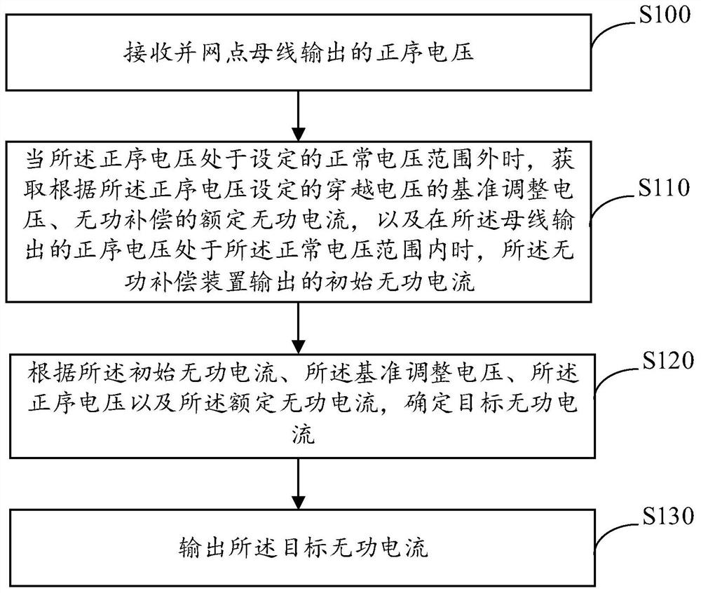
[0043] Next, the control method of dynamic reactive power compensation of the present application will be introduced in detail, please refer to figure 1 , figure 1 A schematic flowchart of a control method for dynamic reactive power compensation provided in an embodiment of the present application, the method includes:

[0044] Step S100: Receive the positive sequence voltage output by the grid connection point bus.

[0045] Specifical...


PUM


Abstract

The invention discloses a dynamic reactive power compensation control method, device and equipment and a readable storage medium, and the method comprises the steps: firstly receiving a positive sequence voltage outputted by a grid-connected point bus connected with a reactive power compensation device, and if the positive sequence voltage is out of a normal voltage range, indicating that a power system is in a fault state at the moment; if yes, the adjustment reference voltage of the ride-through voltage set according to the positive sequence voltage, the rated reactive current of reactive compensation and the corresponding initial reactive current when the positive sequence voltage is within the target range can be obtained, and the adjustment reference voltage of the ride-through voltage set according to the positive sequence voltage, the rated reactive current and the initial reactive current can be obtained according to the received positive sequence voltage and the obtained reference voltage, the rated reactive current and the initial reactive current. And determining a target reactive current to be output in the current fault state. Obviously, the output target reactive current can be dynamically adjusted according to the actual condition of the power system, the situation that the same set reactive current is output under all fault conditions is avoided, dynamic reactive adjustment is achieved, complex faults can be better adapted, and the stability of the power system is improved.

Description

technical field [0001] The present application relates to the technical field of power systems, and more particularly, to a control method, apparatus, device, and readable storage medium for dynamic reactive power compensation. Background technique [0002] Reactive power compensation is a technology that improves the power factor of the power grid in the power supply system, reduces the loss of power supply transformers and transmission lines, improves power supply efficiency, and improves the power supply environment. [0003] The rapid development of the power grid has brought opportunities for the wide application of reactive power compensation devices, which have become an important equipment for reactive power support in the power system. However, at present, the reactive power compensation device connected to the power system has a relatively weak ability to deal with complex faults. During complex faults, phenomena such as overcurrent and overvoltage are prone to occ...

Claims


Application Information

Patent Timeline
Patent Type & Authority Applications(China)
IPC IPC(8): H02J3/18H02J3/16
CPCH02J3/18H02J3/16
Inventor 叶萌胡云李晶黄立滨陈志聪郭海平赵宏伟朱益华尚慧玉李书勇王历晔罗超刘婷曾冠铭苏明章郭天宇
Owner GUANGZHOU POWER SUPPLY BUREAU GUANGDONG POWER GRID CO LTD
Why Eureka
Try Eureka