Large metallurgical slag pot and manufacturing method thereof

A metallurgical slag, large-scale technology, applied in the field of large-scale metallurgical slag tank and its manufacturing, can solve the problems of large slag block, difficult to assemble and disassemble the grid, difficult slag separation, etc., to prevent sintering, reduce the difficulty of separation, and reduce labor intensity Effect

Pending Publication Date: 2022-07-15
WUGANG REFRACTORY CO LTD
View PDF0 Cites 0 Cited by
  • Summary
  • Abstract
  • Description
  • Claims
  • Application Information

AI Technical Summary

Problems solved by technology

[0007] The purpose of the present invention is to address the shortcomings of the above technologies, to provide a large-scale metallurgical slag tank and its manufacturing method, which solves the problem of large slag blocks, and at the same time solves the problem that the grid is difficult to assemble and disassemble, and is difficult to separate from the slag

Method used


Image

  • Large metallurgical slag pot and manufacturing method thereof
  • Large metallurgical slag pot and manufacturing method thereof
  • Large metallurgical slag pot and manufacturing method thereof

Examples


Embodiment 1

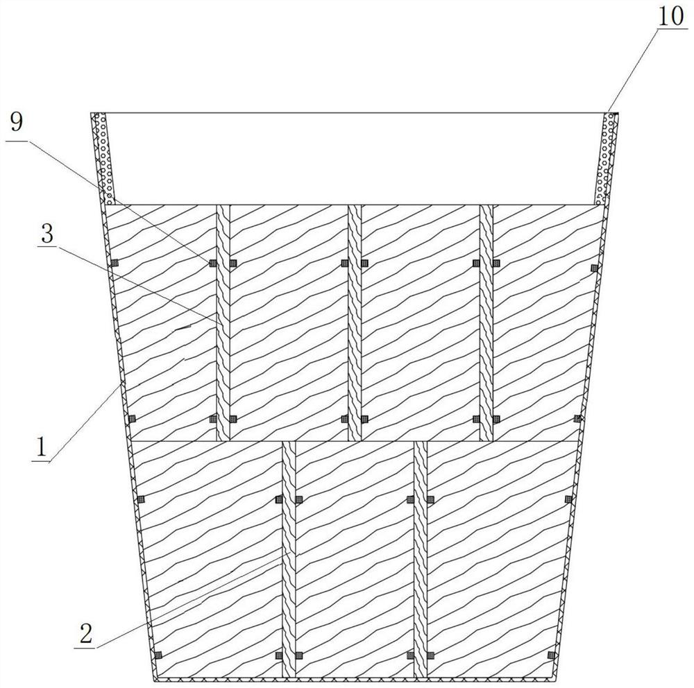
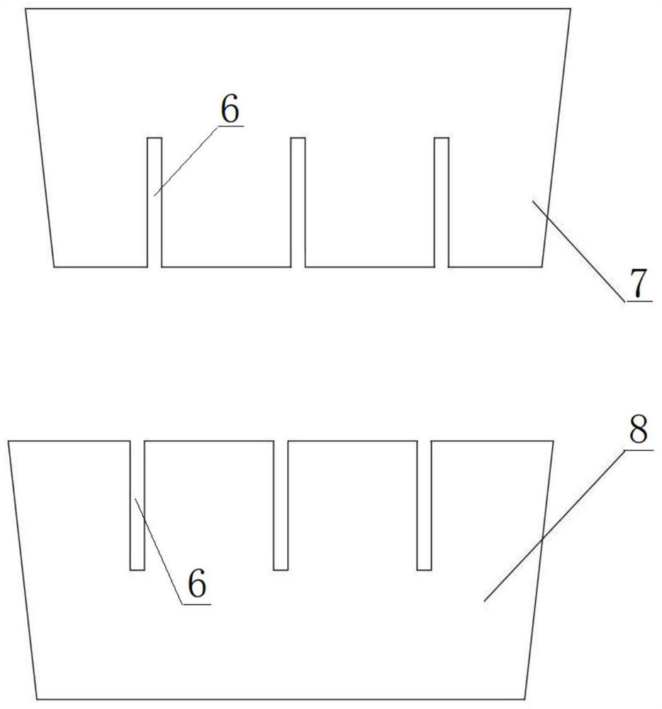
[0039] like figure 1 As shown, a large metallurgical slag tank includes a tank body 1. The tank body 1 is provided with a lower grid structure 2 and an upper grid structure 3 from bottom to top, and the lower grid structure 2 is a well-shaped structure with two horizontal and two vertical. , the upper grid structure 3 is a three-horizontal and three-longitudinal structure, the lower grid structure 2 and the upper grid structure 3 are processed by grid refractory material, the tank body 1 is processed by the tank body refractory material, and the interior of the tank body 1 There are grid positioning clamps 9 for positioning the lower grid structure 2 and the upper grid structure 3, and the tank body 1 is provided with beading bars 10 around the inner side.

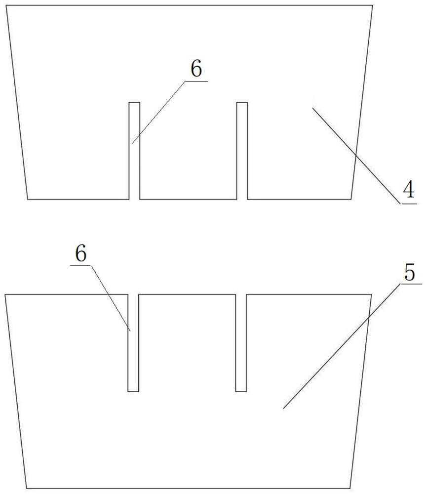
[0040] Among them, combined figure 1 and figure 2 As shown, the lower grid structure 2 includes two horizontal lower refractory prefabricated panels 4 and two longitudinal lower refractory prefabricated panels 5. The ho...

Embodiment 2

[0057] like figure 1 As shown, a large metallurgical slag tank includes a tank body 1. The tank body 1 is provided with a lower grid structure 2 and an upper grid structure 3 from bottom to top, and the lower grid structure 2 is a well-shaped structure with two horizontal and two vertical. , the upper grid structure 3 is a three-horizontal and three-longitudinal structure, the lower grid structure 2 and the upper grid structure 3 are processed by grid refractory material, the tank body 1 is processed by the tank body refractory material, and the interior of the tank body 1 There are grid positioning clamps 9 for positioning the lower grid structure 2 and the upper grid structure 3 , and the tank body 1 is provided with beading bars 10 along the inner periphery.

[0058] Among them, combined figure 1 and figure 2 As shown, the lower grid structure 2 includes two horizontal lower refractory prefabricated panels 4 and two longitudinal lower refractory prefabricated panels 5. T...

Embodiment 3

[0075] like figure 1 As shown, a large metallurgical slag tank includes a tank body 1. The tank body 1 is provided with a lower grid structure 2 and an upper grid structure 3 from bottom to top, and the lower grid structure 2 is a well-shaped structure with two horizontal and two vertical. , the upper grid structure 3 is a three-horizontal and three-longitudinal structure, the lower grid structure 2 and the upper grid structure 3 are processed by grid refractory material, the tank body 1 is processed by the tank body refractory material, and the interior of the tank body 1 There are grid positioning clamps 9 for positioning the lower grid structure 2 and the upper grid structure 3 , and the tank body 1 is provided with beading bars 10 along the inner periphery.

[0076] Among them, combined figure 1 and figure 2 As shown, the lower grid structure 2 includes two horizontal lower refractory prefabricated panels 4 and two longitudinal lower refractory prefabricated panels 5. T...


PUM


Abstract

The invention relates to the technical field of ferrous metallurgy, and discloses a large metallurgical slag ladle which comprises a ladle body, a lower-layer grating structure and an upper-layer grating structure are arranged in the ladle body, the lower-layer grating structure and the upper-layer grating structure are both formed by processing grating refractory materials, the ladle body is formed by processing ladle body refractory materials, and the grating refractory materials comprise, by weight percentage, 10-20% of refractory materials and 10-20% of refractory materials. Comprising the following components in percentage by weight: 50%-70% of recycled silica bricks, 5%-20% of a carbon-containing regenerated material, 5%-20% of an aluminum regenerated material, 3%-15% of calcium aluminate cement, 0.1%-0.5% of a water reducing agent and 0.05%-0.2% of an anti-explosion agent, and the tank refractory material comprises the following components in percentage by weight: 50%-70% of recycled silica bricks, 5%-20% of the carbon-containing regenerated material, 5%-20% of the aluminum regenerated material, 3%-15% of the calcium aluminate cement and 0.1%-5% of a plasticizer. The invention further discloses a manufacturing method of the large metallurgical slag pot. According to the large metallurgical slag pot and the manufacturing method thereof, the problem that slag blocks are large is solved, and meanwhile the problems that the grating is difficult to assemble and disassemble and is difficult to separate from slag are solved.

Description

technical field [0001] The invention relates to the technical field of iron and steel metallurgy, in particular to a large metallurgical slag tank and a manufacturing method thereof. Background technique [0002] The metallurgical slag tank is an important container for metallurgical steel slag or iron slag in iron and steel metallurgy. After the metallurgical slag tank is slag formed in the steel mill or iron factory, the metallurgical slag tank is transported to the processing workshop, and the metallurgical slag tank is turned over to pour out the slag. In order to solve the problem that the steel slag or iron slag is too large and difficult to handle, most steel mills have installed grids of various shapes in the metallurgical slag tank to separate the steel slag or iron slag into small pieces of similar size, which are convenient for subsequent processing. However, the current metallurgical slag tank still has the following problems: [0003] 1) For large metallurgica...

Claims


Application Information

Patent Timeline
IPC IPC(8): C21B3/10B23P15/00C04B35/66
CPCC21B3/10B23P15/00C04B35/66C21B2400/072C04B2235/5436C04B2235/5427C04B2235/5212C04B2235/402C04B2235/349C04B2235/96Y02P10/20
Inventor 徐志华王志强王心一郑吉红
Owner WUGANG REFRACTORY CO LTD
Why Eureka
Try Eureka