
Three-dimensional circular weaving machine

A three-dimensional circular loom and host technology, used in circular looms, looms, textiles, etc., can solve the problems of unclear opening, high cost, and large number of warp yarns, reduce the amount of waste yarn in the process, improve product quality, The effect of reducing manufacturing costs

Pending Publication Date: 2022-07-12
XIAN YINGLIKE ELECTRIC TECH CO LTD
View PDF0 Cites 1 Cited by
  • Summary
  • Abstract
  • Description
  • Claims
  • Application Information

AI Technical Summary

Problems solved by technology

The main difficulty in weaving thick prefabricated bodies with 3D circular looms is that the opening is difficult. Due to the large thickness of the 3D prefabricated body, the number of warp yarns is much larger than that of flat fabrics. The severe crowding between multiple groups of warp yarns near the weaving mouth makes the opening unclear. Thereby causing great difficulties to the design of the opening mechanism and the completion of the opening action
The tubular three-dimensional looms described in the prior art essentially have one row of openings, that is, all warp yarns are transposed at the same level of the loom, which makes it difficult to complete the predetermined action in actual use.
At present, most of the carbon fiber tubular circular weaving prefabricated parts with commonly used weaving structures such as 3D 2.5D are hand-woven. Due to the difficulty of opening during weaving, it is necessary to leave warp yarns several times the useful length between the tension wire and the weaving mouth for workers to remove. Operation, resulting in the actual warp consumption is far greater than the product needs, the waste is very serious! Manual weaving also requires the cooperation of multiple people, and it is difficult to control the tension and weft density of the yarn, resulting in unstable quality of the three-dimensional prefabricated body, low production efficiency and high cost

Method used


Image

  • Three-dimensional circular weaving machine
  • Three-dimensional circular weaving machine
  • Three-dimensional circular weaving machine

Examples


Embodiment 1

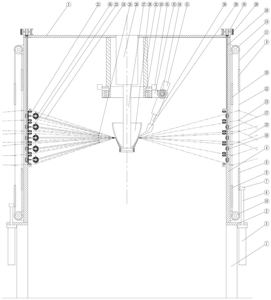
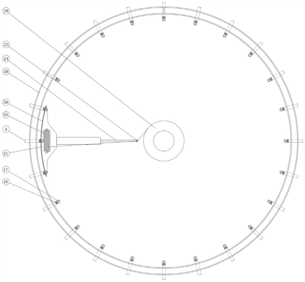
[0087] see figure 1 , figure 2 , a 2.5D single-row 5-shuttle three-dimensional circular loom with i=1, comprising a main engine, a warp creel, and a warp yarn tension component, the warp creel is distributed around the main engine, and a warp yarn tension component is arranged in the middle of the warp creel and the main body, and the warp yarns extend from the warp creel. The yarn bobbin is drawn out and sent to the host through the warp tension component;

[0088] The main machine includes a frame, an opening device, a weft insertion device, a tightening device, a core mold driving device, a driving motor and a control device. This machine can weave 5 layers of warp yarns and 8 sets of warp yarns with shallow interlocking veilless 2.5D three-dimensional tubular fabrics.

[0089] The frame includes a column 1, an upper support plate 3 and a lower support plate 2 and a group of support columns 4 distributed on the same circle to connect the upper support plate and the lower...

Embodiment 2

[0097] see Figure 9 , a 3D three-dimensional circular loom with i=1, comprising a main engine, a warp creel, and a warp yarn tension component, the warp creel is distributed around the main engine, and a warp yarn tension component is arranged in the middle of the warp creel and the main engine, and the warp yarn is drawn out from the bobbin of the warp creel , sent to the host through the warp tension component; the host includes a frame, an opening device, a weft insertion device, a tightening device, a core mold driving device, a driving motor and a control device.

[0098] The frame includes a column 1, an upper support plate 3 and a lower support plate 2 and a group of support columns 4 distributed on the same circle to connect the upper support plate and the lower support plate;

[0099]The opening device includes 2m semi-circular heald frames 59 coaxially distributed, 2m lifters and heald frame limit slots arranged on the support column 4, where m is the number of warp...

Embodiment 3

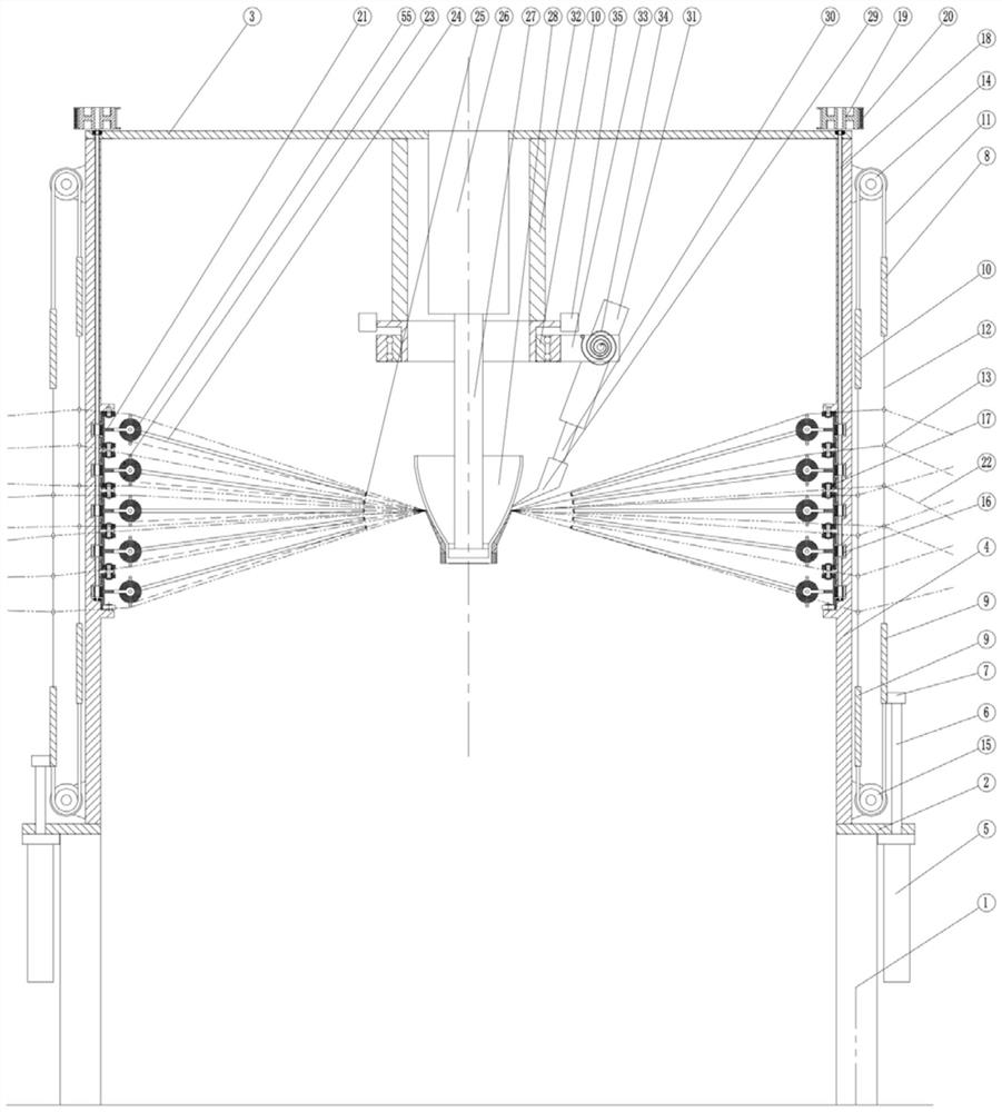
[0106] see image 3 , Figure 4 , an enhanced 2.5D three-dimensional circular loom with i=2, comprising a main engine, a warp creel, and a warp yarn tension assembly, the warp creel is distributed around the main engine, and a warp yarn tension assembly is arranged in the middle of the warp creel and the main engine, and the warp yarn from the warp creel The yarn bobbin is drawn out and sent to the host through the warp tension component; the host includes a frame, an opening device, a weft insertion device, a tightening device, a mandrel driving device, a driving motor and a control device.

[0107] The frame includes a column 1, an upper support plate 3 and a lower support plate 2 and a group of support columns 4 distributed on the same circle to connect the upper support plate 3 and the lower support plate 2;

[0108] The opening device includes 8 semicircular heald frames 59 in total, 4 or 2 lifters 5 and a heald frame limit slot set on the support column 4, 8 semicircula...


PUM


Abstract

A three-dimensional circular weaving machine comprises a main machine, a warp creel and a warp tension assembly, the warp creel is distributed on the periphery of the main machine, the warp tension assembly is arranged between the warp creel and the main machine, and warp is led out of a spool of the warp creel and sent to the main machine through the warp tension assembly. The main machine comprises a rack, an opening device, a weft insertion device, a tightening device, a core mold and a core mold driving device; the opening device is arranged on the outer side of the rack, the weft insertion device is arranged on the inner side of the rack, the core mold driving device is arranged in the rack, and the core mold is connected to the core mold driving device; according to the invention, multiple rows of openings are adopted, so that gathering of warp yarns at a single opening is effectively dispersed, and the problem of difficult opening caused by crowding of the warp yarns is solved; the multi-row and multi-column shuttles are adopted, and the effects of low rotating speed and high yield are achieved.

Description

technical field [0001] The invention belongs to the technical field of circular looms, in particular to a three-dimensional circular loom. Background technique [0002] The ablation-resistant and anti-scour lining and outer heat insulation layer of the diffusion section of solid rockets were all manufactured by the tape winding process in the past. It will delaminate and fall off. The best way to solve this problem is to use carbon fiber preforms woven by three-dimensional circular looms. The main difficulty in weaving thick preforms with a three-dimensional circular loom is the difficulty of opening. Due to the large thickness of the three-dimensional preform, the number of warp yarns is much larger than that of flat fabrics. Therefore, great difficulty is caused to the design of the opening mechanism and the completion of the opening action. The tubular three-dimensional looms described in the prior art are essentially one row of openings, that is, all warp yarns are tr...

Claims


Application Information

Patent Timeline
IPC IPC(8): D03D37/00D03D49/14D03D47/34D03D49/26D03C9/00
CPCD03D37/00D03D49/14D03D47/34D03D49/26D03C9/00
Inventor 吉少波李杰李凤珍朱晓军李凤枝胡国斌李骥冲
Owner XIAN YINGLIKE ELECTRIC TECH CO LTD
Learn More